The 2026 Sidecar Rally registration is now open! Click here: USCA 2026 Rally Registration Form
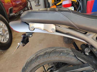
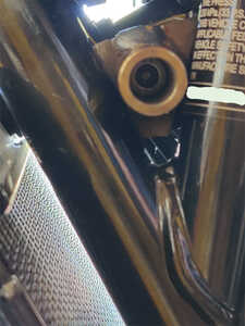
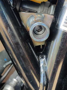
Final plate shaped and welded on.
Reefed on it pretty good with a 12" adjustable wrench. Seems pretty solid. Would have liked more triangulation between the three mounting bolts, but it is what it is.
All back together for now. The footpeg bolts will get replaced with studs, anti-vibration washers and nuts. Would have liked to do that with the rear footpeg bracket bolt, but it would stick out too far.
Still to come is drilling the holes and welding studs in to attach the Heim joint plate. Then it can get painted in a flat black, and should pretty much "disappear".
Meantime, materials are starting to show up to build the other three mounts.
Hold my keyboard and watch this! 🙃
Forgot to mention one important thing. Master cylinder clearance. Didn't want to add any complexity regarding servicing/replacing the rear master cylinder. Also wanted to ensure there is enough clearance so the plate doesn't flex into contact with the master cylinder. Hence the need to stack the three plates. Also puts the plates in tension with each other which helps limit flex, over using a single bent plate shaped to fit.
Hold my keyboard and watch this! 🙃
@scott-h Hey Scott, are you thinking of building a similar plate on the left foot peg mount, and then running a connecting tube across to the one you just did on the right? Would probably really help with torsional stiffness along the axis parallel to the length of the bike frame.
Maybe not needed, but a thought.
Posted by: @ben-franklin@scott-h Hey Scott, are you thinking of building a similar plate on the left foot peg mount, and then running a connecting tube across to the one you just did on the right? Would probably really help with torsional stiffness along the axis parallel to the length of the bike frame.
Maybe not needed, but a thought.
That would have been a great way to do this. 👍 Could have the mount further back for better clearance around the heel area as well. It would require a different exhaust system eliminating the resonator that blocks this section under the bike. Otherwise it would require a big and ugly subframe assembly ruining the looks of the bike, and changing the handling when detaching the sidecar for two wheeled fun.
The section of frame where the bracket is attached has a through bolt motor mount, and just above is the swing arm pivot bolt. So the frame is pretty stout in this area. The way the bracket is welded mitigates flex along the X,Y & Z axes. It is a series of lap joints towards the middle of each piece. The weak point with this design is lateral twisting, because of the lack of triangulation of the mounting bolts. Using studs for the footpeg mount will allow a higher clamping force along the whole footpeg bracket mating surface. That is larger than it looks. Paws crossed it will be enough.
Hold my keyboard and watch this! 🙃
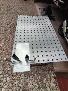
Moving on to the upper rear mounting. This layout table is nice to work from. Both cutting out & cleaning up the brackets, as well as welding.
Shaped out the two brackets, and put the bends in to fit the off set lugs (one bracketfor each side).
The subframe on this bike is very stout, and fairly short, so it should provide a solid point for the upper rear bracket. Also keeps the rear strut out of the way of a passenger.
Hold my keyboard and watch this! 🙃
Not much accomplished on this short day. Started on the upper bracket bag mounting loops. Just some 1/4" rod.
Still have one loop to make for the left bracket. Then more welding, finish sanding and paint for the left side.
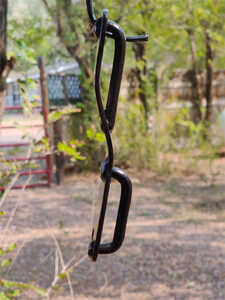
Thinking about adding a helmet hook below the left loop (in picture above). Need to do some research to get ideas. A locking hook would be nice.
Right bracket still needs more fabrication to mount the Heim joint plate.
Hold my keyboard and watch this! 🙃
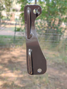
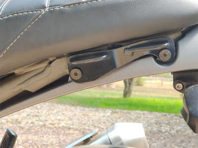
Left side bracket complete (replacing the passenger grab rail). Need to get some bolts to mount it on the bike. Right side upper strut bracket will look similar. Right side bracket is taller, and will have one additional hole with a nut welded behind (or possibly a stud welded) for the upper strut plate mounting.
Left bracket mounted on the bike with temporary fasteners for a bit of context to how the right side will look, without the sidecar mounted.
Hold my keyboard and watch this! 🙃
I really like the dual or even triple use bracket concept.
Let's see.
Passenger grabs?
Pannier mounts?
Sidecar mount point?
Helmet lock point?
Should we go for a spare fuel/water bracket as well?
Anymore suggestions?
My two absolute favorites would be:
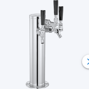
Beer tap holder! 🤩
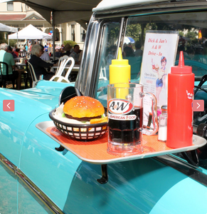
Car Hop Tray holder.
Not necessarily in that order, depending on how hungry I am. 😉
Hold my keyboard and watch this! 🙃
Well.
Seeing as motorcycle's are inherently unstable.
And your fitting a sidecar to solve that sparticular problem.
Then the only thing is when you fall off reaching for a refill.
No damage to the machine so OK.
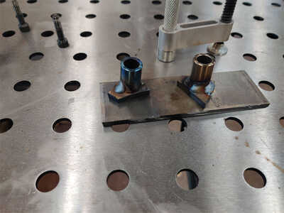
Starting on the front upper blocks. This is in replacement of the $400 CNC blocks from the CAD drawing I attempted. The only downside is there is not enough room in the frame to weld all the way around short tubes. Plenty of penetration on the areas that were welded, so it should be strong and durable enough.
The hex head cap bolts just fit inside the tubing, so careful placement on the base plate was critical. The fit up table sure made that easy. Step one done for under $10. 😎
Hold my keyboard and watch this! 🙃
They Fit. 🙂 With them bolted in place, there may be a bit more room for weld work. They have to go in slightly raised and then slide down into place, so need to be careful with the size of weld so they don't end up rubbing the frame tubes.
Hold my keyboard and watch this! 🙃
As the bike mounts are getting fabricated I've been considering the connect points between sidecar & bike.
Pretty common to use Heim joints or Clevis joints. Allows for the flexibility of adjustments, and a somewhat firm connection. But it is a bit flexy, and transmits spikes (NVH) directly into the bike.
Thinking the upper strut mounts would be fine as clevis mounts. They aren't as critical as the lower connection points.
I'm considering using a polyurethane based joint for the two lower mounting points. Like these:

This would help absorb transient spikes between the sidecar and bike, limiting the stress on the bike frame, while also limiting the flex of Heim joints. Downside is there is very minimal misalignment, so the mounts have to be very carefully built, and the rig setup has to be pretty spot on during the build.
These specific units are for the front trackbar linkage on a Jeep, so they are pretty stiff.
Another option is the narrow version Johnny Joint, which does have a much higher misalignment spec for adjusting the rig's alignment. but creates a mount that is 2-1/2" wide (1/2" wider than these XFlex units). That additional width creates higher twisting forces on the mounts and mounting points of the bike.
These first world "Too many options" decisions are tough... 😉
Hold my keyboard and watch this! 🙃
@scott-h Hey Scott,
For what it is worth, my experimentation with reducing flex in the coupling of the sidecar to the bike has led me to believe that "no flex is good flex."
Every change that i have made to BBTSG that reduced flex, either in the subframe, frame, mounting hardware, and yes, bike frame, has resulted in noticeable improvement in handling.
Next time I build an AT subframe, I will forego heim joints and just use solid rodends in double shear mounting configuration.
I think you can use heim joints with decent results, if big enough and solid enough, but a little up front design work to make things line up, and they are not needed. They just facilitate easy alignment of universal chairs to a specific subframe.
I still have heims in BBTSG, but have them under enough tension that they don't get to flex much. Next round will be solid.
Just a random thought or two. ![]()
Yeah, I'm not really a fan of Heim joints between the sidecar and bike either. Certainly it makes setup and adjusting the sidecar alignment easier. Fabricating mounts is less critical. Reduces costs/increases profits for commercial ventures.
Flex is a fascinating area of study. To your point, did you know that Honda changed the frame in '24 to optimize handling for the two AT models? From the Honda Press release:
"Frame
All Africa Twin versions use a steel semi-double-cradle frame, with optimized rigidity/flex characteristics for challenging situations like riding with luggage, riding two-up, or off-road riding. For example, rigidity around the steering head has been optimized to enhance front-end feel and grip, and the main spars are optimized to enhance longitudinal rigidity for good handling under braking. The frame’s pivot plates are 600MPa high-strength steel. The rear cross pipe, which connects the left and right pivot plates in the upper area, is located in line with the shock stroke, resulting in a direct transmittal of surface information to the frame, for good rear-wheel feel."
Hold my keyboard and watch this! 🙃
- 29 Forums
- 11.8 K Topics
- 93.3 K Posts
- 1 Online
- 5,604 Members
