Mike
I didn't realize you wouldn't have room to use the webbing, not real familiar with the 1100. on the 1500 that webbing comes down below the seat. I have to say that set up you are using looks pretty good. My only concerns are the angle it's at is going to cause constant side forces on the frame tube and the fact that you drilled through the tube has created a weak point. I hope I'm wrong, but I fear in time that tube will crack or even break
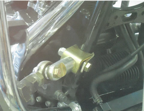
if this is the MV clamp you have on the front you shouldn't have to worry about it rotating, that's the one I had on the 1500 and it is rock solid.

Mike
I didn't realize you wouldn't have room to use the webbing, not real familiar with the 1100. on the 1500 that webbing comes down below the seat. I have to say that set up you are using looks pretty good. My only concerns are the angle it's at is going to cause constant side forces on the frame tube and the fact that you drilled through the tube has created a weak point. I hope I'm wrong, but I fear in time that tube will crack or even break
if this is the MV clamp you have on the front you shouldn't have to worry about it rotating, that's the one I had on the 1500 and it is rock solid.
I've owned several 1500's and that webbing area is quite larger and easier to access than on the GL1000 or the GL1100. I wish someone would come forward with some pics of that certain mount on the GL1000. With long term usage testimony.
I have seen several pictures of that specific mount being done similar to what I am doing, but none any other way....Yep, that one is not the one I am the most proud of, but I took pics I found and tried to improve it a bit. IF, IF it were to ever crack or break, my idea is to make a plate that covers that ENTIRE side of the bike, the area were the side cover usually goes. have it to where the rear master cyl can still be accessed, Paint/stripe it to match the bike, then weld that mount to the plate. Just did not want to go that extreme at this point as quite a few pics of the approach I chose seem to be out there in use.
Yes I did drill to get the bolt through the frame, But I am also going to Tig weld that bolt on both sides which will make it stronger than just drilled and probably even more strong than it was from the get go. Now where I am doing all this is on the very edge of the web weld, not in the middle of the tube so hoping that all will be ok.
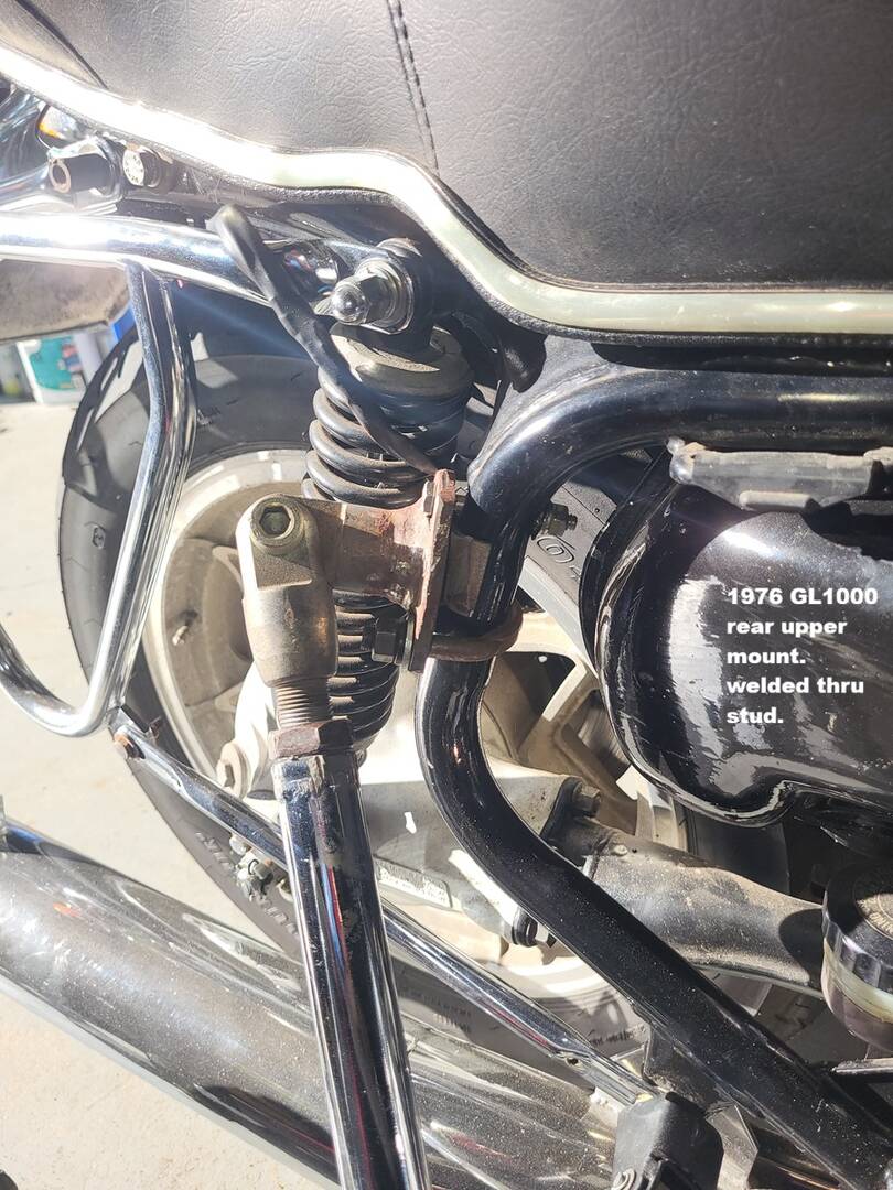
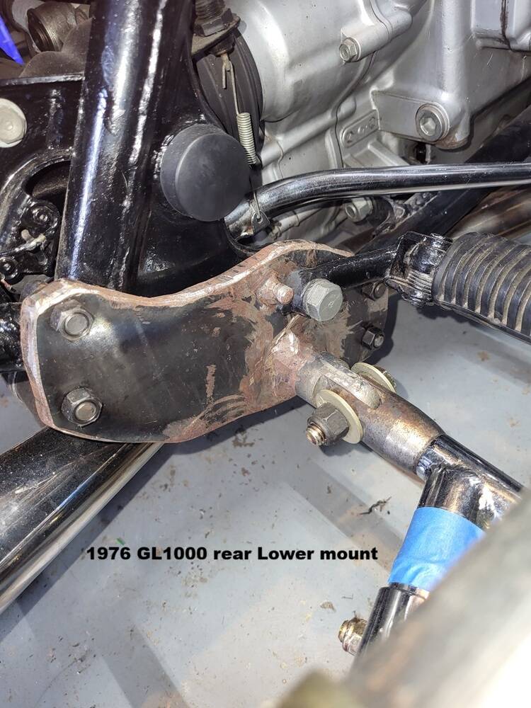
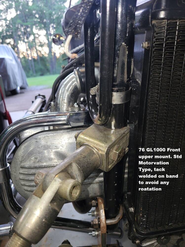
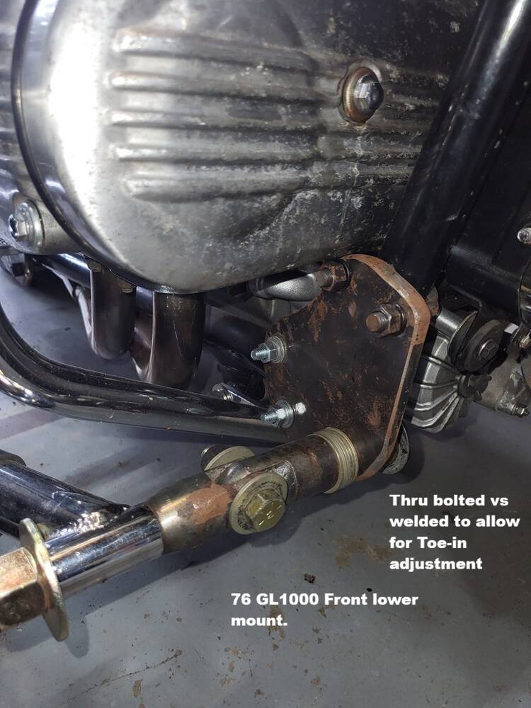
As you bring up the mounts, here is a pic of each of mine.
Was going to post this once I took them off, painted and could photo both sides. Several on the back side have sections of half pipe being used as saddles for stable/ non rotatable mounting in certain areas. All steel plating is 3/8". The U-bolts being used are all 3/8" diameter with most of them being 2ton Truck universal joint straps. In the pictures everything is still in the rough, some bolts are not the final ones going to be used for final install, they were what I had on hand when designing. Having followed long time sidecar builder J Sweet for several years on FB, I followed his advise as to how he has built mounts for over 50 years with no failures.
Mike
1976 Honda GL1000 & Motorvation Formula II
2009 Honda GL1800 Roadsmith
2022 MotoGuzzi V85TT
Gotta say you do excellent fabricating work, really looking forward to seeing the rig when it's done
Yep, I have had 3 1500's still have 1, a 96 trike that I bought that had been sitting in a barn for about 5 plus years. Went through it and now my wife rides it.
had a 97 that I put the FII on, we rode it for years and I sold it at a Rally a few years back, I really enjoyed that set-up. had a 6 gallon tank behind the seat with one way check valve in line in front of a pump, hose ran to a fitting in the tank so I could fill it on the fly, could ride almost 300 miles between fill-ups
Thank you sir for the compliment. When it comes to my construction projects as well as metal work, I probably way overkill the situation. But, luckily nothing I have ever built has failed.
Oh yeah, I have had many 1500's myself. Other than the rebuilding of carbs these days, due to the modern fuel, they are still to me one of the best touring bikes ever built. I just recently got rid of one I had for over 18 years, was sort of sad to see it go as I had traveled so much with so many friends over the years. All the friends are gone, now so is that bike.
Cool idea on the added fuel tank, my Roadsmith GL1800 trike has that option available, but mine does not have it. After a recent 7k mile cross country trip, I am planning to add it in the near future, just not the RS version as to me its a bit too pricey for just a plastic tank and a filler spout. I may do something similar with this SC rig, if I see I ride it alot.
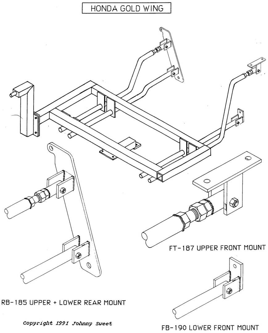
I put out a question on the FB "Sidecars are fun" group about the rear mount on a GL1000. JSweet almost immediately replied with his tech drawing on the subject. Dont know why I never thought to ask that before there. By his drawing it appears he used to attach his sidecars to GL1000's back in the day on the same vertical plane, however once I asked him the mount points he stated the bar went from the Foot peg bolt to the upper shock bolt. But, at the same time also stating his sidecars back in that day only weight about 165lbs. I am thinking a MV Formula II weighs quite a bit more. But possible still an idea in the making for something different that what I am doing...Hmmmmmmm?
Mike
1976 Honda GL1000 & Motorvation Formula II
2009 Honda GL1800 Roadsmith
2022 MotoGuzzi V85TT
That is interesting. seems you would need to use at least a 3/8 flat bar to prevent flexing, also maybe U-bolt clamp it to the frame tube somehow near where your current clamp is. I think that would make it solid for a heavier car and give you a straight on connection. from the pic of your bike it looks like it would have to go behind the frame tube. could be the angle of the picture but the shock looks recessed from the frame. that could create some challenges
Well JS recommended 3/8 for all mounts, after using such for 50 years I trust he knows what is best, so 3/8" plate is what I am using. I Think his design was intended for passenger foot peg and shock bolt as the angle from the Drive foot peg up the shock is much more extreme of an angle than the drawing depicts.
Yes the threaded section of the shock where the acorn nut finishes it out, IS a bit recessed. BUT to me I am thinking that stud is a bit too small for this application that and it would also need to be bushing 'ed outward to remove that recess. I am still deep in sanding/painting/sanding agian/striping/painting again at the moment. But when I get all that done I plan to re-evaluate that one mount for other options.
If I do something similar to JS design. I may just add another outward facing stud in the same area as the Shock stud, then work from there.
searching online for weights as well as taking in my mod work I am figuring my sidecar is going to be in the 250lb + range without a passenger. Supposedly a stock from the factory unit is in the 200-220 range. That has me thinking JS design proven at 165lb just needs to be a tad bit beefier.
Mike
1976 Honda GL1000 & Motorvation Formula II
2009 Honda GL1800 Roadsmith
2022 MotoGuzzi V85TT
Yes, I like the added stud idea much better. I feel the 220 to 250 is a good number. I'm pretty sure ours was right about 250,with the added weight of the frame for the flip nose, the 6 gal tank I added and a couple lbs. for the brake components.
I used about 30' of the 1" sq tubing and it weighs 2.2 lbs per foot so that is an easy 60lbs extra. added hardware and tidbits maybe another 5. I am also going to do a 1 of a kind windshield/wrap around canopy made from spruce glassed over & painted and light tinted 1/4" Polycarbonate for the windows. Side windows may slide? and top it off with a foldable/removeable Hard top similar to the Targa top I have on my classic Porsche. Mainly my small dog would ride with me IF he gets into it....with this approach he can roam freely inside the area, with the idea its much too tall for him to get out. If its raining the Targa can go on it. I also added a intake vent into the front sloped area of the top tub that can be opened/closed either forward or reverse Similar to the old Cowl vents on the old pickup trucks of the 40-50's. I usually avoid the incredible hot parts of the year for riding anyway, but this vent along with sliding side windows will surely provide tons of through breeze for anyone. If I see its not enough, I'll just add a small ice water cooled evaporator coil to it as I Never ride without a large cooler anyway, and I did install an added hitch to the rear of the chassis just for a cooler. I built a ice water vest a few years back and ran it for a few trips to our NC mtn home dead of summer....it did great other than my tshirt stayed soaked due to the condensate.
By time all that done will be probably more around 275+ lbs. Those massive Hannigan dual seaters I have no doubt are probably much heavier than this will be. Right now my bike & chassis has taken a few trial rides with a large 48" plastic tote with 150 lbs of sand in it. Handles great with plenty of power even at 65+ mph.
Back to work....had to start putting things together on the Sidecar Tub tilt part as I have tons of freshly painted things all over my shop and running out of room.....yeah I know, champagne problem as my wife calls it.
Mike
1976 Honda GL1000 & Motorvation Formula II
2009 Honda GL1800 Roadsmith
2022 MotoGuzzi V85TT
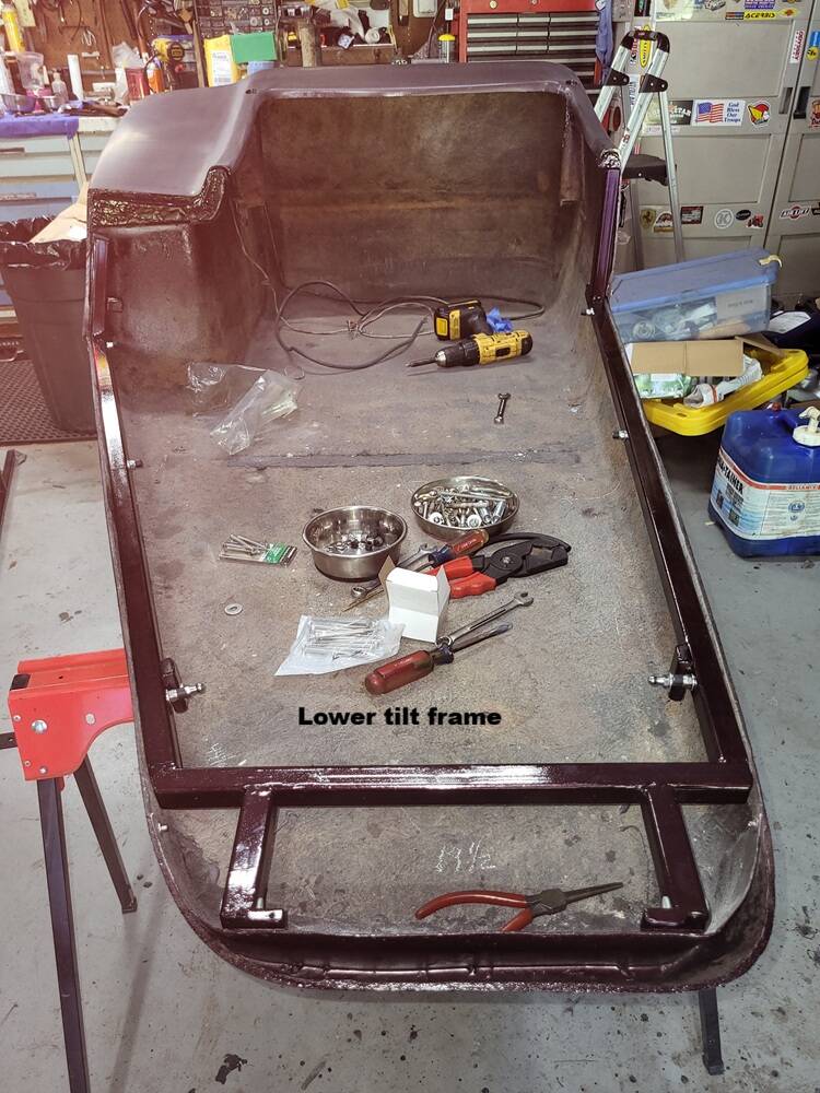
As good a time as any to show all the details of the tilt frame I created. I had to have a place to store the tub top as I continue painting other bike items.
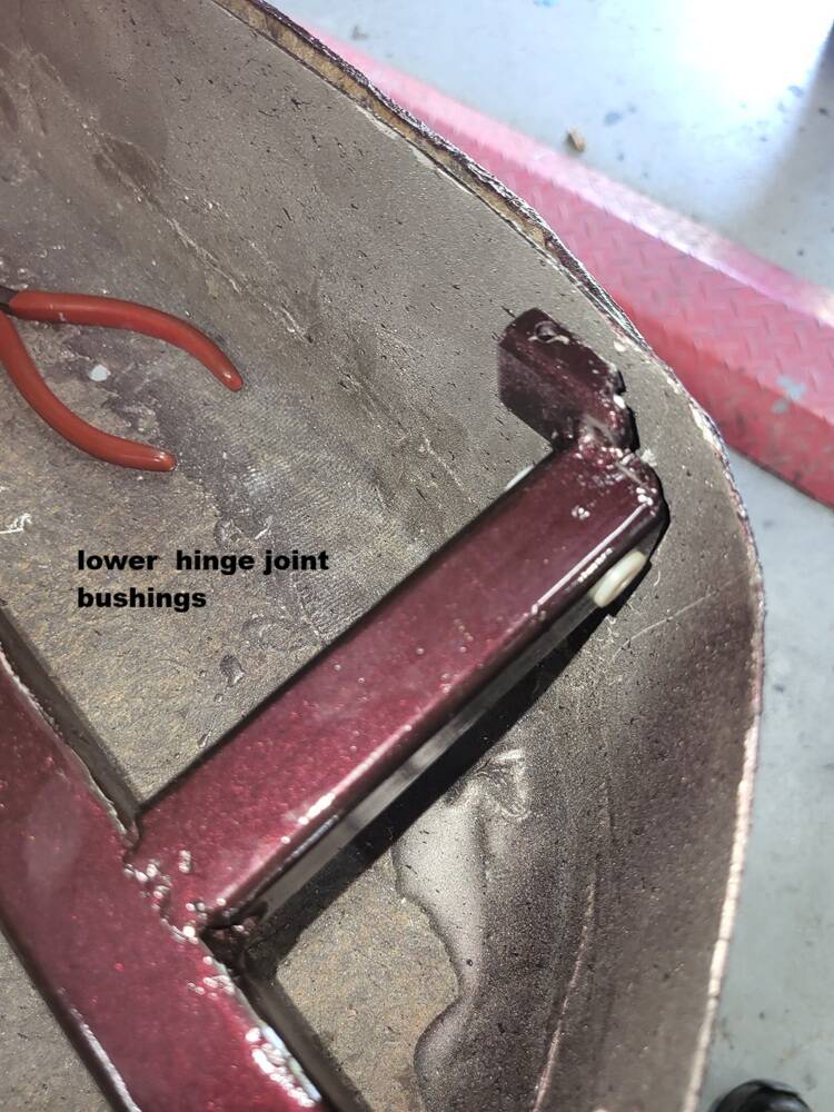
Here we have the bottom frame assembly installed in the bottom tub. Also one of the forward arms that the dual pivot hinge attaches to. Using Nylon bushings on all pivot point hinge holes to ensure solid alignment, minimal metal wear/rust created over time, and a good place to hold some lube for longevity movement. All mounting an pivot hardware is stainless steel.
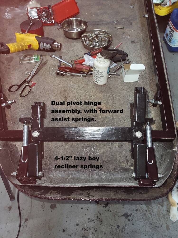
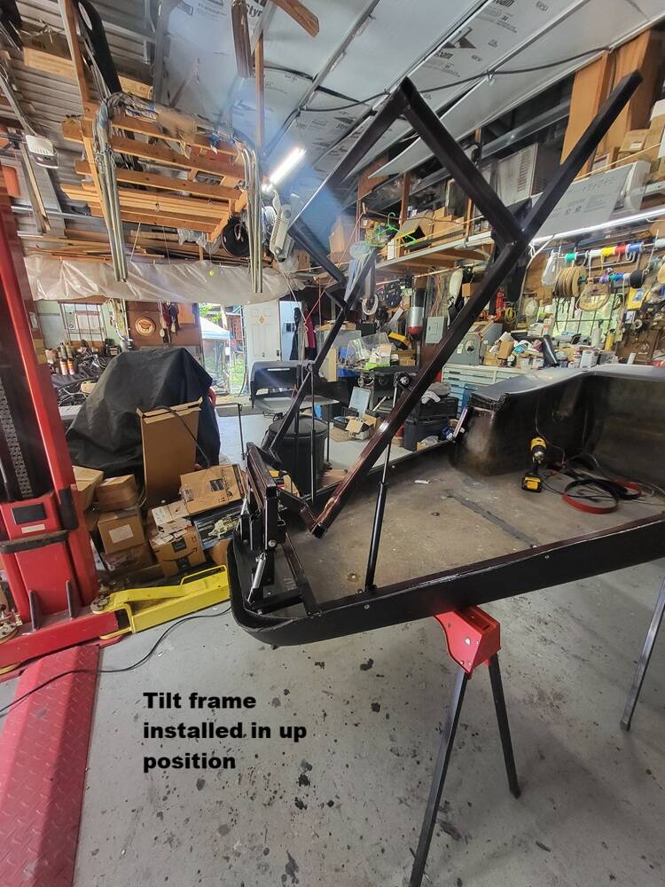
Dual pivot hinge assembly, views from all points. In order for this to work proper and not have the top tub grab the front of the bottom tub during tilting, the Top has to go forward at the same time it goes upward. Pictures of this online were near non-existant. I hope to one day see a factory unit to see just how it works vs mine. Creating this was the hardest part of the build to date. After numerous attempts, I had to walk away for a few days to think. One evening while sitting in my living room recliner it came to me. The leg section of the recliner was doing what I needed the top tub to do. Using recliner springs, forward assist is provided while the lift pistons do the lifting.
All of the Factory such units I have seen picture of online. There are 2 sets of lift pistons, 2 pointing forward and 2 backwards. Thinking that one does a similar move to create the lifted front end.
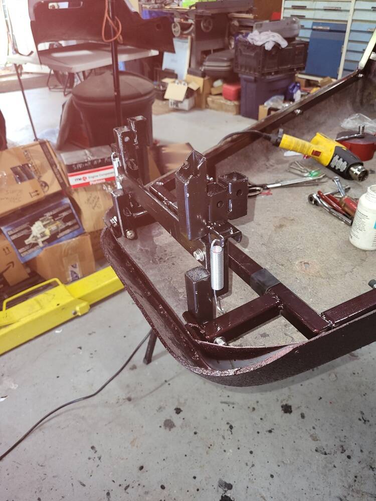
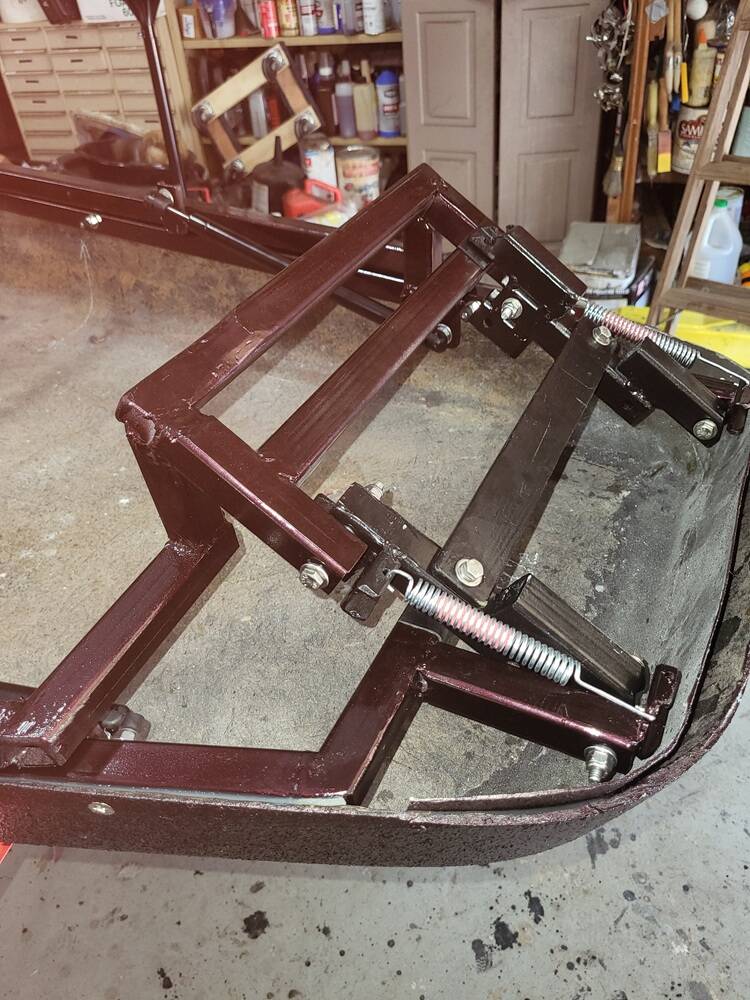
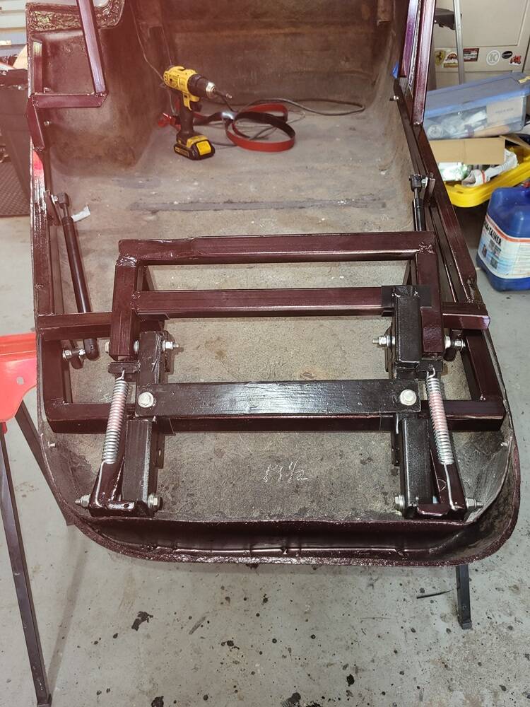
Top frame attached and in down / up position
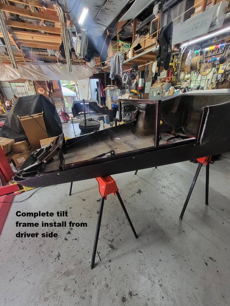
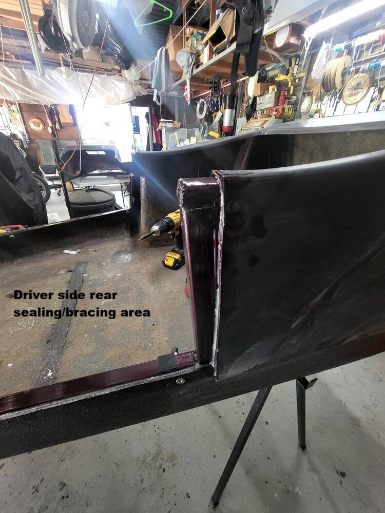
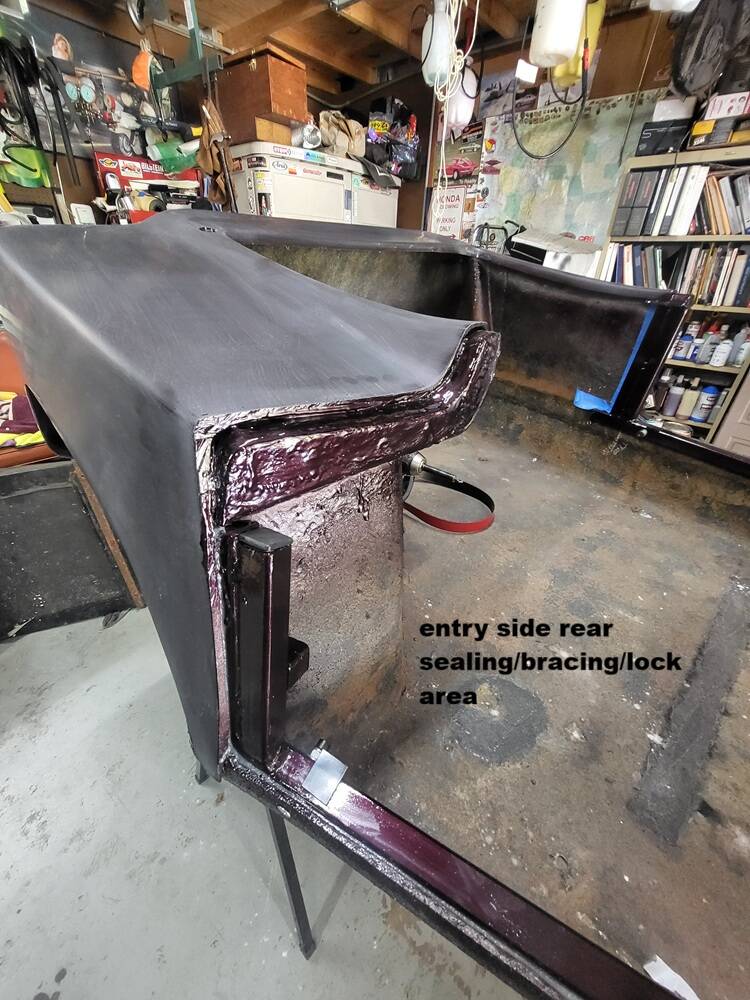
End joints where rear of top tub joins front of bottom tub. Rear overlap seal area, vertical bracing to ensure no flex in the area when top tub is down. Entry side has latch extension for eventual entry turn handle/lock. Rounded shaped were created using Spruce then glass coated.
Top & Bottom tub joined down showing Overlap of top to bottom tub IF fixed tub is split properly.
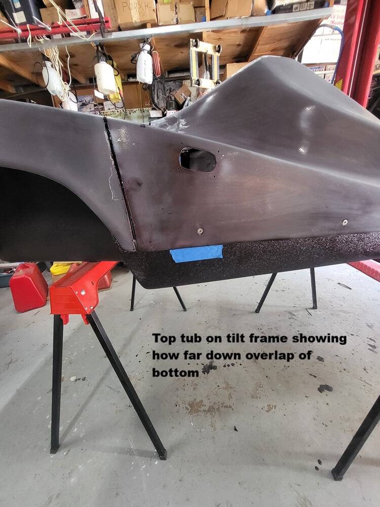
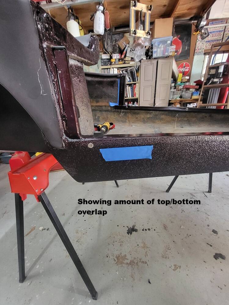
Top tilted upward showing full mechanism from behind as well as side and forward view. Hole in top tub will be a air intake vent, similar to what was used in 40-50's Chevy / Ford Cowl cab intake vents. Hole in entry side is for a small recessed handle for lifting to open.
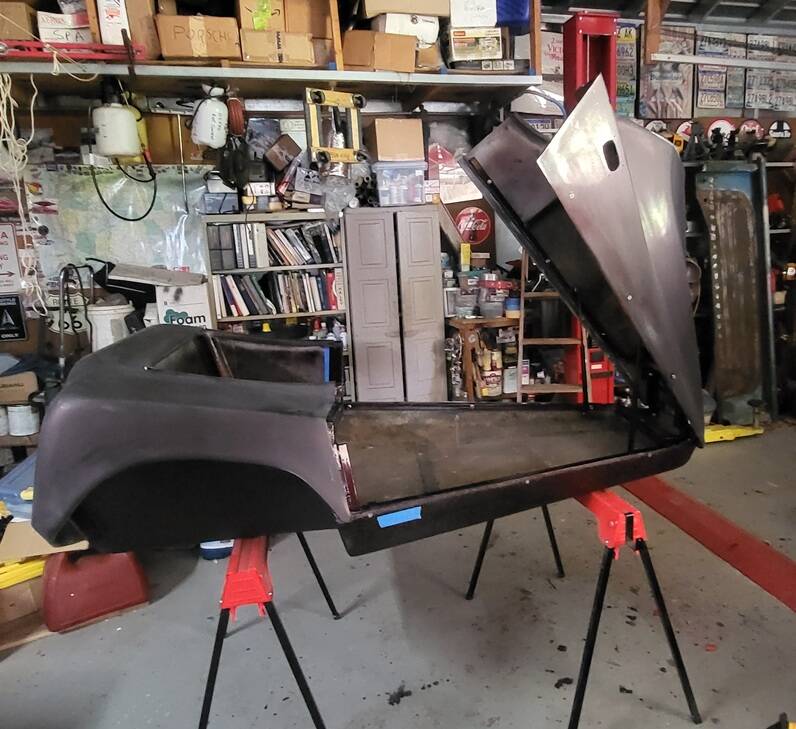
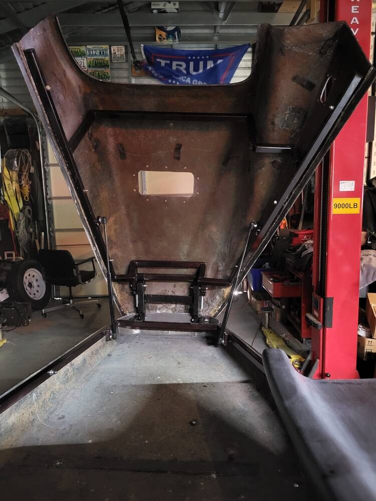
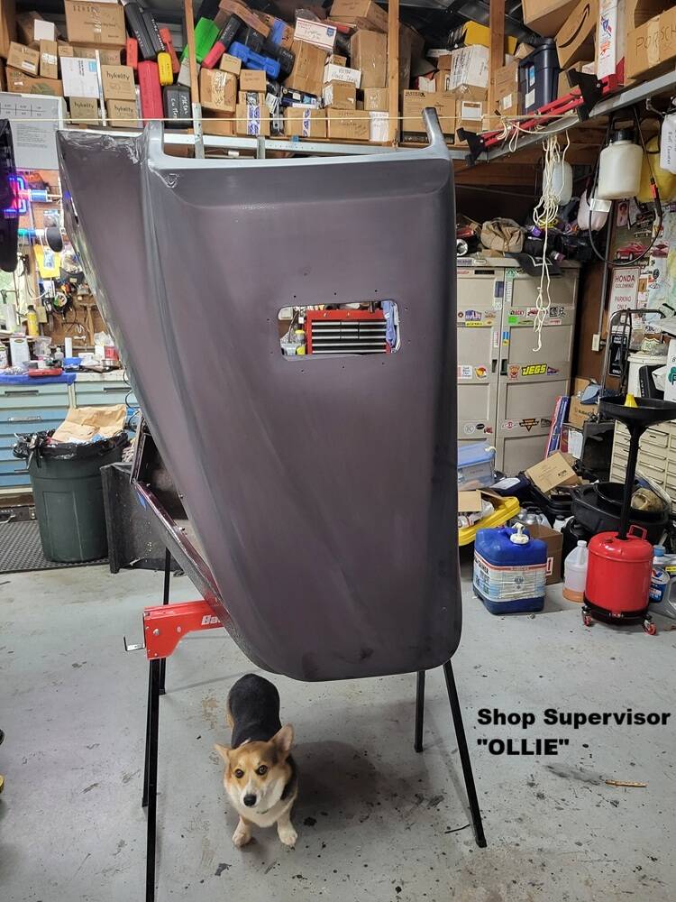
I Hope this information will help any in the future that might give thought to creating a Tilt front from a fixed tub Motorvation Formula II.
Still lots more I have to do, but this gives the splitting of the tub and tilt mechanism that I created in detail.
Mike
1976 Honda GL1000 & Motorvation Formula II
2009 Honda GL1800 Roadsmith
2022 MotoGuzzi V85TT
Well there was some thought went into that little project.
I totally get the walk away part.
Seems it's an integral part of creativity for us mortals.
We go start something but can't see inside as to how much creative juices are available today.
Goes great for a bit then it's walk time.
Unless you want an inferior product then by all means press on.
The gas struts I've used several times now.
I have a guy I go to half way across the city.
To date I've had to go back 2 out of the 3 times to get him to reduce the pressures.
They deal in Newton's which is a bit foreign speech to me.
A couple more projects and I may get it.
Trying to work out what the springs do.
Is it a double hinge arrangement.
So it swings clear of the lip?
Lets talk about your gas pistons first.
That is actually a very easy to solve problem. Sir Isaac Newton doesn't have much to do with it.
If you know the weight of what you are wanting to lift, you source the pistons accordingly.
In my case I already had a set of pistons that were rated at 100 lbs. I knew this was way to much, but they were what I had on hand during my design phase. They were near impossible to pull down and the 1-2 times I did get them down as I started to go back up, they damn near launched my top tub to the moon. I weighed my Top frame and my top tub. Together they came to about 38 lbs so I obtained 2- 40lb lift pistons. When you figure pistons their weight range is designed to work as a pair. Now, if you have the OE Motorvation design, that has 4 lift pistons, quite clearly in a few pictures I found, the 2 sets are quite different from one another. The rear are larger and longer, the front are shorter and smaller. BUT, I am thinking after all the work it took to make mine lift AND clear that lip, 1 set lifts the other set pulls fwd. With those I would have no idea how to weight spec, unless it were to say the lift would be 40 and the fwd would be 10-20
As for my design you sort of need to see what put me down this path.
I spent near 2+ years occasionally yes, researching and thinking about how I was going to do this build. Both the unique features of my bike for its resto after a 36 year barn sleep, as well as what all to do to properly restore a MVF2, but also how to make it tilt. Some might say " why didnt you just buy a tilt model"....I would say to those what the hell is the fun in that?...but seriously, I got this MVF2 for $400, once I got to researching just that, I realized I had a hell of a deal on my hands and went and bough it. Restored ones I see all over the web selling for $5K+. My entire life/career path has been all about creation and problem solving, I'm retired and days in my shop is what I do when not traveling. I hate paying people or business's to screw me.
Anyway, there are very few pictures anywhere online of how MVF2's tilt, other than optionally they could. I was able to find this "1" picture of that mechanism. (zoomed in from a picture of the inside of a unit)
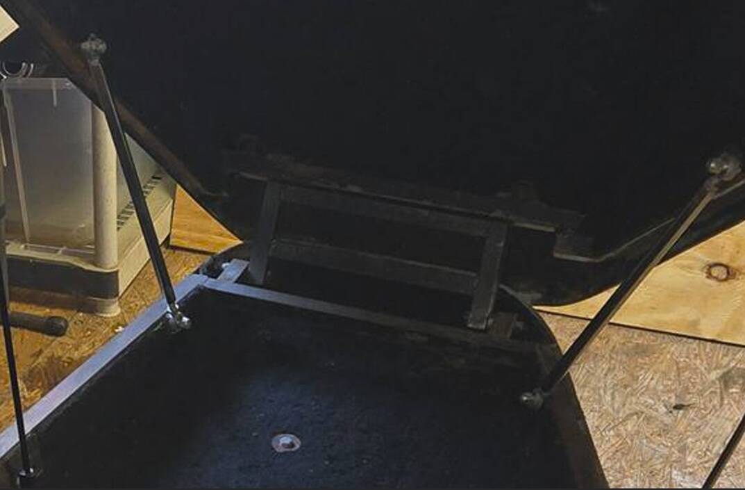
Looks simple enough I thought, but I never took into consideration that once the tub was split, if you tried to single plane pivot it, the top of the tub would dig into the bottom of the tub very soon after the lift process started. The overall frame I had already figured out, that was simple just time consuming. To the best of my ability I 100% recreated exactly what was in this picture. But clearly there were motion features I could not see. This design with its unknown feature, only resulted in a very low angle partial lift and eventual destruction to the front of my tub. I started cutting down the front lip of the bottom tub....to a point I had to stop, and still it would not clear. I tried moving the pivot point as far forward as it would go, still it would hit. In this picture that pivot point is 1.5-2" from the cross frame, not near 4 " as mine eventually ended out being. Mine could have been 1.5-2 had my vision happened sooner.....frustrated, walked away for a few days and did some work on the bike. But still constantly thinking.
As stated earlier, one evening sitting in my recliner it came to me....in order for my recliner foot section to function, it moves forward/outward then upward. I got up and flipped the recliner over for inspection. The recliner uses springs that have stored energy (stretched out) when the foot section is in the down stored position. They sort of lock in place as they have moved over a certain arc'd movement. The recliner lever helps them over that arc, then the stored energy is released and the foot moves outward, while continued movement and the weight of your ass helps move it upward.
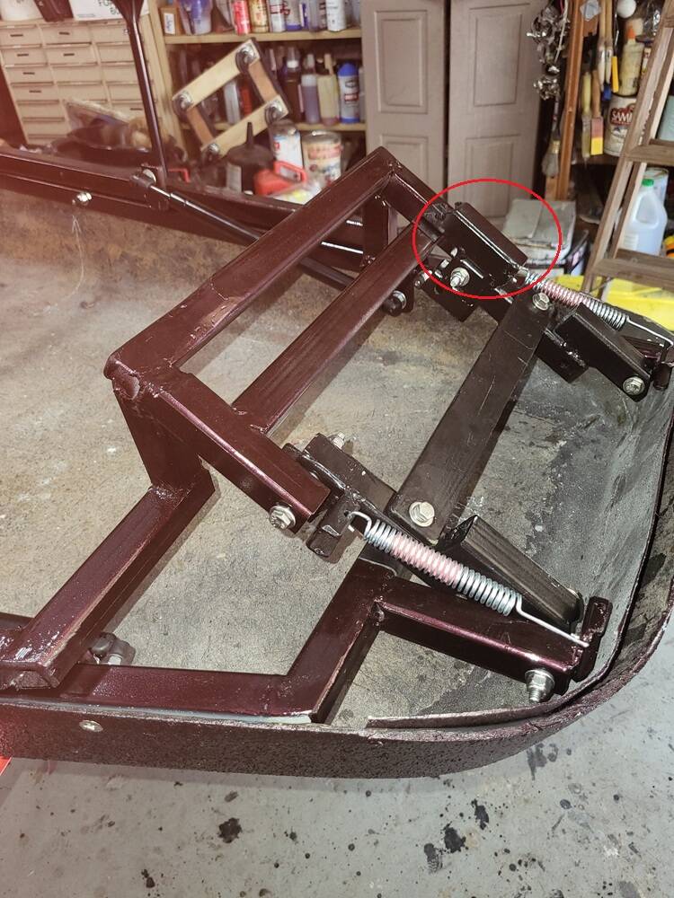
Now lets look at this picture. In it the top tub frame is in the down position. In this position the springs are stretched out and they have stored energy. The round red circle is a metal arm that acts like the lever on the recliner, as you start to raise the tub, the upper tub frame pushes on this arm to help those springs get over that certain locked spot, then the stored energy gently assists with enough of a forward movement to help clear that lip. when all is together and buckled up its very hard to see this action, as its not a lot. But if the top tub is off AND the springs are not in place, you yourself have to manually give it that forward motion, and you have to hold it in that small forward state before the lift pistons will raise it up and OVER the lip.
In my design, a 2 direction movement Forward & upward, cannot be done with a single pivot. It takes 2 pivots.
The entire black section is one large mass acting as a hinge. in 3 pieces for easier install, 1 for each side and a cross brace to make the mass rigid. At each end is a pivot point. 1 at the bottom where it joins the bottom tub frame is your overall lift angle pivot. The 1 at the top joins the top tub frame and provides that forward motion pivot.
As stated earlier....from an engineering perspective I really want to see and understand the OE design.
Mike
1976 Honda GL1000 & Motorvation Formula II
2009 Honda GL1800 Roadsmith
2022 MotoGuzzi V85TT
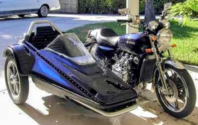
somebody mentioned naked goldwings. Above is a rig I had a few years back.
Very nice.....Lester mags, corbin gunfighter and a very nicely done Terraplane.....Hope ya didnt ride it nekkid!
Mike
1976 Honda GL1000 & Motorvation Formula II
2009 Honda GL1800 Roadsmith
2022 MotoGuzzi V85TT
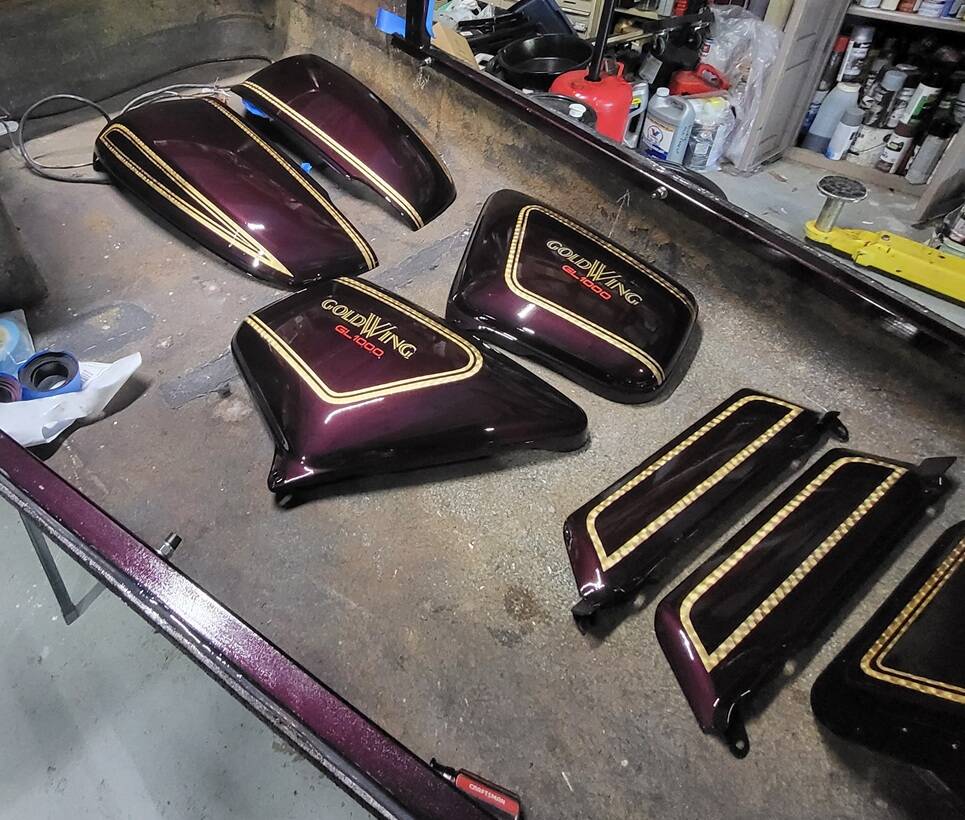
A small taste of the finished package vision.
Mike
1976 Honda GL1000 & Motorvation Formula II
2009 Honda GL1800 Roadsmith
2022 MotoGuzzi V85TT