
Soooooo…. Miles are you admitting membership in this club?
who is Miles?
Mike
1976 Honda GL1000 & Motorvation Formula II
2009 Honda GL1800 Roadsmith
2022 MotoGuzzi V85TT
Well your detailed description of how you split the body shows a lots of experience.
I won't offer any more ignorant advice.
Liking where you are heading.
No expert at all in this new world of sidecars...any advise or ideas on anything always appreciated....BUT, I've been custom building just about anything all my adult life. I have more hobbies than any human should have. Nothing I wont try to accomplish, and always enjoy good challenge in just about anything.
Home builder/designer, cabinet maker, upholstery, electrician w/computer science degrees, 40 years of industrial electrical, computer automation/engineering. ASE certified just for my hobbies of classic cars/bikes, metal worker.....just to name a few. Learned to do for myself at a very young age as its just the way I was raised. Been retired now for near 4 years and stay busier than a 1 armed paper hanger.
Mike
1976 Honda GL1000 & Motorvation Formula II
2009 Honda GL1800 Roadsmith
2022 MotoGuzzi V85TT
Long day on the road with my wife, our weekend thing. But took a few more pics.
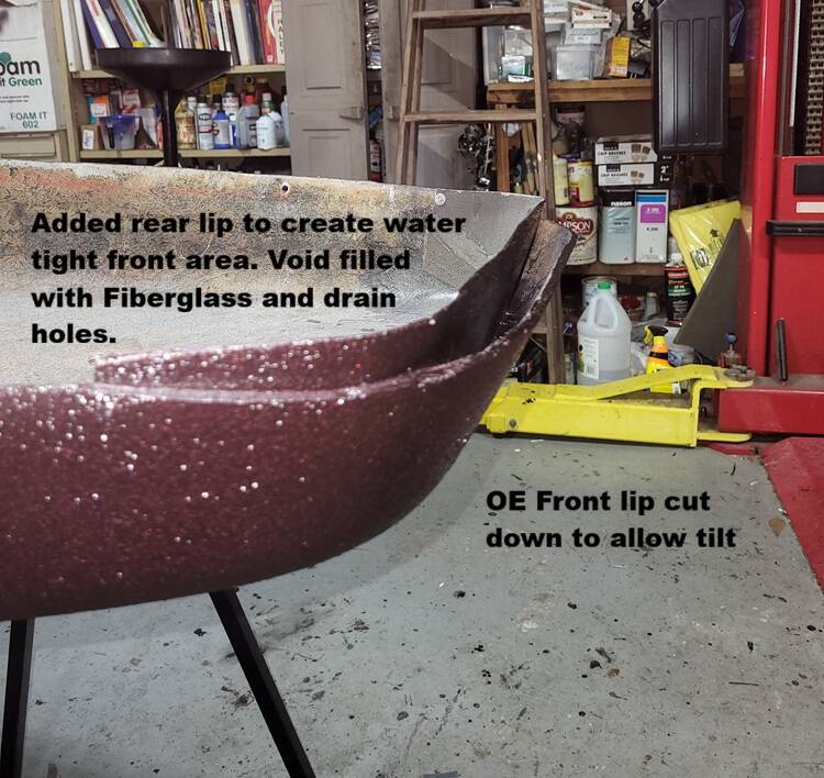
Here is where I cut down the front OE lip after the split so the top of the tub, would tilt without rubbing the two halves. Then I added a second wall/lip a bit behind that cutdown in order to still seal the foot area from any water. ON top of that new wall I will add that afore mentioned seal. The void between the cutdown OE wall and the new higher wall is filled with fiberglass matting and resin about 1/2 way up, then I added drain holes downward but in front of the new wall near the bottom for any water that makes it into that void to escape.
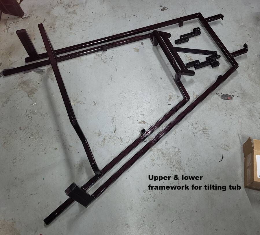
Here is my framework for both the Bottom and top halves of the tub. Each will be attached with countersunk stainless screws around the perimeter of each corresponding half. All metal is 1" x 1/8" square tubing (tig welded). Which added approximately 65lbs to the weight of the tub. As so many mention adding ballast during non passenger riding this should sort of help with that. My wife no longer rides due to numerous back surgeries, but my dog sure likes riding on our sxs so hoping he will take to this. Hound plus any added gear and this extra weight should have this as a quite stable setup.
Back to painting some more items tomorrow and the next day. Then a few days of striping, followed by more clear coating. So be a while before any more build updates.
Mike
1976 Honda GL1000 & Motorvation Formula II
2009 Honda GL1800 Roadsmith
2022 MotoGuzzi V85TT
Hello Mike
that is some very impressive work. we had a Motorvation II for a few years and loved it. Following your build here. Do you know if your camber control arm is the newer round design or the square. if it is the square I would start looking now to try to find the newer round arm. Maybe Gary Greene or Michael at Bald Eagle sidecars could find one. The square end design was a weak design, mine broke while turning off the highway and the car dropped like a rock and bottomed out on the frame. scared the begibies out of me, luckily I was just a few miles from home so I was able to nurse it back and not have to tow it.
Hello Mike
that is some very impressive work. we had a Motorvation II for a few years and loved it. Following your build here. Do you know if your camber control arm is the newer round design or the square. if it is the square I would start looking now to try to find the newer round arm. Maybe Gary Greene or Michael at Bald Eagle sidecars could find one. The square end design was a weak design, mine broke while turning off the highway and the car dropped like a rock and bottomed out on the frame. scared the begibies out of me, luckily I was just a few miles from home so I was able to nurse it back and not have to tow it.
Thanks, trying to do it all proper after a few years of researching while it collected dust over in the corner. Last few big bike 2 wheel long distance trips told my body its time to migrate to a new way, so bought a trike last winter for this years trips as well as started this project.
My camber control arm is the round, internal worm gear type ( I assume). I tried to get the arm part to seperate for inspection but never could get it to do so. The rest I fully disassembled it all the way to the naked motor checked all, cleaned, regreased the drive gears, blew out the motor, polished commutator ring, brushes looked near new as well as wiped everything down with Sharkhyde metal seal to avoid any rust, installed new seals on the case....works great.
Overall chassis was stripped to the last bolt, stripped/painted, all new Grade 8 hardware, wheel bearings/seal, very little if any wear on anything. Only worn item I found was the wheel seal rubber had gotten a bit hard. I dont think this rig saw much road time in its prior life. Guy I bought it from had it for over a decade in a barn when he abandoned the thought of the resto I am doing, and just went and bought a new Hannigan.
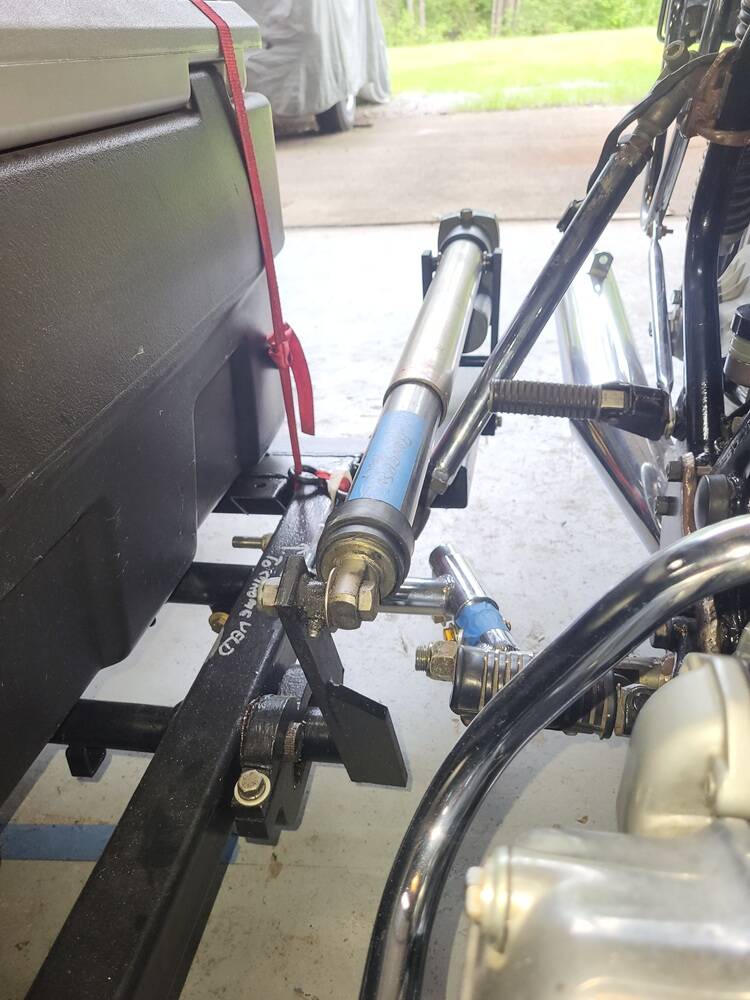
Yeah that thought of what happened to you has crossed my mind. I was going to fab a metal bar, probably using a tractor drag link bar (adjustable) that could take the place of the motor assembly should such ever happen. Keep it on the rig as part of the road emergency gear. Ive had an issue or two on occasion when out LDR, either me or a time or two with others ive ridden with. With exception of a BMW that burned out a final drive bearing, all bikes have always gotten home on their own power. Having a sidecar or the way I have rigged my trike, offers a solo rider LOTS of extra space to store all sorts of possible roadside emergency stuff. I guess the many years of being a boy scout has stuck with me for life....be prepared.
Mike
1976 Honda GL1000 & Motorvation Formula II
2009 Honda GL1800 Roadsmith
2022 MotoGuzzi V85TT
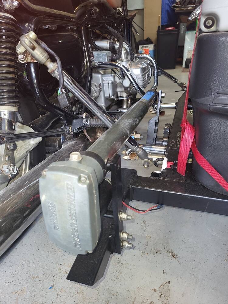
not sure we are talking about the same part. I am referring to the torque rod that goes from the motor side over to the wheel, the torque arm is inside the tube under the car and actually lifts the wheel, in your second picture the bracket connected to the tilt motor, when it is pushed or pulled it rotates the torque arm that runs under the car in a tube that is part of the frame, that is the torque arm I am referring to, you would have to remove it to know which style it is. the old style if memory serves me correctly was like flat bars stacked and that is what created it's ability to act like a torque arm, the problem was all that flexing would cause the bars to break. after a couple would break the whole thing would collapse and the car would fall onto the frame. if we are talking about the same part and you have checked it................ nevermind 😉
OK after looking at the first picture I see something I want to ask about, is that top rear support rod connected to a clamp on the frame. If it is I would like to suggest a better and safer point of contact. I can't see the front top mount in the pic it's not on a standard u clamp mount is it

OK after looking at the first picture I see something I want to ask about, is that top rear support rod connected to a clamp on the frame. If it is I would like to suggest a better and safer point of contact. I can't see the front top mount in the pic it's not on a standard u clamp mount is it
Ace @aceinsav, I saw the same things you saw regarding the clamps on the frame, and had the same concerns.
Two Million Mile Rider
Exploring the World in Comfort
this is an example of where and how the rear mount should be on the goldwings, on the 1500 the knuckle wouldn't line up on i's own so I had to use a tapered shim so the bolt would be square to the webbing in the frame. you just have make sure to install a thick washer on the back side of the webbing and once everything is aligned tighten the crap out of it. had mine mounted for years and it never budged
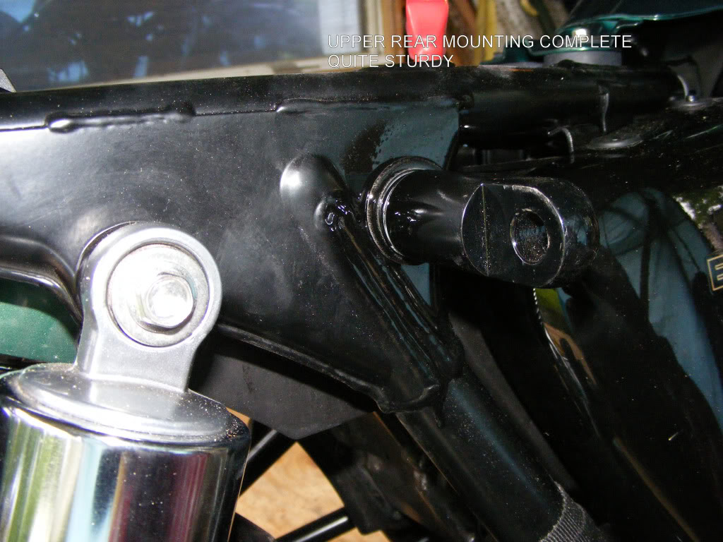
@aceinsav My bad thought you were talking about the actuator that controls the camber.
My torsion axle is in fact a 1 " round solid bar with splined ends. Took out also during the resto, cleaned checked for cracks no issues.
Mike
1976 Honda GL1000 & Motorvation Formula II
2009 Honda GL1800 Roadsmith
2022 MotoGuzzi V85TT
That’s good news, I haven’t ever heard anything about the new style rod failing
In all my searching, I never saw a mount like that on any GL1000, But did on a few GL1500's, but then again there is not a lot of pictures out there at all for the 1000's. I saw several that mounted the top rear in a similar spot that I did. One that made a montrous mount between the shock and seat mounting area that also stuck way out. I did not care for that approach and would no way work with the saddle bag system. I did not see anyway to access that web area with the seat and the shock in the way. As I also plan to keep the samsonite bags and working around those for that mount has been a challenge.
Yes you did see a clamp. But its a 2 ton Truck Universal joint clamp,3/8" od . the same style J. Sweet uses when he has to use a clamp. Not some cheesy muffler clamp. Im using them in a few locations as added clamping. I do have it as close to the web as I could get it, But what you dont see on that specific mount, in that picture is the fact that the 3/8" steel plate, with the Factory MV mount base welded to it, is not only clamped on the bottom side, but on the top side a welded through-bolt goes through the frame. No way its gonna rotate. IN this pic I am still using a temp 5/16" bolt not welded, but was planning to weld and more than likely used a G8 3/8". All mounts still in rough state not finished except for the one factory MV one I am using.
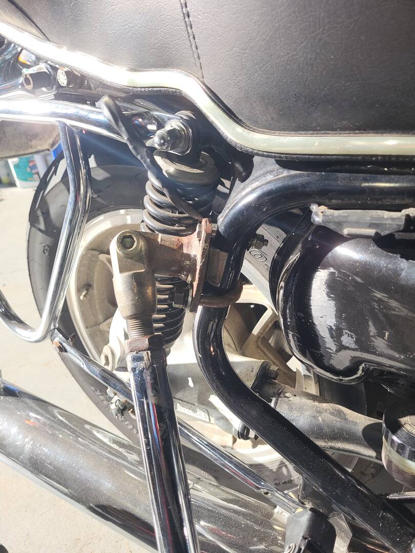
As for the top mount on the front I am using the factory Motorvation UStrap setup but have it tack welded also to avoid any rotation. Mounted in the same location I saw many pictures do the same. Many using the similar clamp, a few making a custom plate steel approach and UBolts.
The two bottom mounts, The rear is another 3/8" steel plate fix through bolt mounted to the Foot peg hole but with a longer bolt then 2 added Truck universal clamps one in front of that bolt, and one behind. MV heavy yoke welded to it.
The front lower is also a 3/8" plate with MV yoke welded to it, mounted in the area of where the frame makes its turn from Vertical to Horizontal. I saw several pictures online on GL1000's all using that spot. At the moment I am using 2 of the truck universal clamps to hold that one, but I may also add a through the frame welded stud, same as I did for the rear top.
I'm open to any suggestions for better ways specific to GL1000's, but as MV from the factory used nothing but those goofy strap clamps, I see what I am doing as much stronger.
Mike
1976 Honda GL1000 & Motorvation Formula II
2009 Honda GL1800 Roadsmith
2022 MotoGuzzi V85TT
@aceinsav are you talking about the suspension torsion spring?
Or springs?
A series of flat springs forming a long square bar spring?
As in the type like early beetles use.
The Chiang's I imported from China years ago had a long round torsion spring connected to the swingarm at one end and to the chassis at the other.
Only had 2 inches of travel.
But length etc can can tune the variables.
A few months back I got in touch with Gary Green that worked for Motorvation sidecars for 40 years. He now works for midwest Sidecars.
My question was in reference to adding a outward shock to act as a damper for bumps Here was his reply. referencing the torsion Axle that is on the MV. At that point I had no idea that the axle in fact also acts as a torsion spring.
I also have a vintage Porsche 911, that has an identical in action torsion bar rear suspension. But also has rear shocks for added dampening. So his reply made perfect sense. Your beetle reference along the same lines.
Mike
1976 Honda GL1000 & Motorvation Formula II
2009 Honda GL1800 Roadsmith
2022 MotoGuzzi V85TT
@aceinsav are you talking about the suspension torsion spring?
Yep I was saying torque but meant torsion rod