The 2026 Sidecar Rally registration is now open! Click here: USCA 2026 Rally Registration Form
@mgv8 Thanks, Brian, I was just searching McMaster last night and had no idea what to call those things!
@ben-franklin Me too.. My hardware guys are very patient with me as I ask for "that thingy that gozonto the end of this shaftey round thing". some roll their eyes a tad ![]()
Posted by: @ben-franklin@mgv8 Thanks, Brian, I was just searching McMaster last night and had no idea what to call those things!
Frequently I start a search on McMaster to help me narrow down the thing I'm actually trying to find. Keywords come up and the part description gets more fine tuned along the way.
Illegitemi non carborundum est!
Well Friends,
Made a little progress with the repairs to Black Betty (that sweet girl) today. Shop was a very pleasant temperature, so pretty much spent the day in it:
Since I had the nice new A arms from TSC, as of last night (THANKS @SIDECARUSA">@SIDECARUSA JONNY AND KENT!!!), I decided to do a little prep work and get them installed. I had delusions of maybe going for a ride, later, but spent far too much time fussing with alignment to really make that happen.
Commentary/observations: Since I have now been able to compare the old DMC A arms, a set of transitional TSC A arms, and the newest next gen A arms side by side. here are my thoughts.
Welding is pretty nice on the TSC generated A arms. The next gen ones that I am now working with are the nicest of the bunch.
The design change to go with a full length clamp seems to be a sound idea. I have observed the failure modes on the two prior sets. They all seem to start at the outside edge of clamp, and propagate around the welds to the cross members. This design should increase the force required to flex the clamp at the weld area under deceleration and acceleration. So good idea.
There are also a pair of triangular gussets added in lieu of the old cross brace. This increased the contact with the clamping surface and should make them resist tearing out, a little more. (maybe a lot more.)
Now to work:
First, since there were plenty of threads in the end pieces (weld nuts?) I decided to shorten the front A arm by about 5/8" or ~15mm. I wanted to do this because it has always been tough to get toe-in and lean-out to work with the top strut lengths and equal length A arms. I always had to crank the front heim joint in as far as it would go, then adjust toe-in with the rear one. Doing that, I still had less than optimum thread engagement with the strut mounting points and end eyes. Almost always right at 5 threads engagement and not really set the way I wanted it.
So...
Looked like the threaded sleave was welded at the outside end (that I cut off.)
So I fused it with the TIG welder and cleaned up the weld face to have a nice surface for the lock nut to engage with.
So next, I bolted the new A arms up, kind of loosely, and dialed in the bike 1/2 degree lean out, supported with 4x4 s, shims, and a jack while I had the hack level front to back and side to side, with the tilt set in the middle of its range.
This was kind of a starting point for screwing with toe-in. I got a little bit obsessive, since when I get the A arms braced, as I will describe in a later update, resetting toe-in will be a little more of a pain in the ass than it is currently.
I also loaded the bike seat up with weights equaling my weight in full gear, after a big lunch and installed the aluminum straight edges for toe-in measurement.
8 tries was the charm. I had been running 5/8" toe-in, and decided that I want to try 13/16" before locking everything into semi-permanent adjustment.
Managed to stay at 0.4 degrees lean-out, decided for no great reason other than imagined aerodynamic improvement, to adjust the front to back angel of the chair to point nose down by 0.4 degrees. Any reason this is a bad idea? I'm thinking it will level out if there is a passenger in the side car, but didn't test it.
Both top struts, and both top mounting points are at maximum length with 5 threads engaged. I definitely need to make some new struts that will give a little more range of adjustment AND have a safety factor for thread engagement. Not sure what the thought process was with old DMC length selection. They are too short for my liking.
Decided that was the stopping point for the evening. Started around lunch-time, finished around midnight. Sheesh, you'd think I was getting paid by the hour, huh?
Here is what it looked like as I went in for dinner... yes, that is a 10 lb sledge leaning up against the tool box. The top front mounting tube had bent forward about 3/4" (19mm) in the festivities on the BDR, and required a bit of adjustment back to straight.
Tomorrow, I will test ride it with the increased toe-in and see if I like it. If yes, then I will lock every thing down tight, and fab up the mystery braces, that are in my fetid imagination, to take some of the torsional load off of the A arm clamps to the lower frame tube.
Stay tuned for the insanity...
Well Friends,
I managed to entertain myself in the shop, again, for a bit, today.
I decided to ride Black Betty (that sweet girl) out and around the county a little, to see how yesterday's toe-in shenanigans has worked out, prior to welding up the braces for the spiffy new A arms.
Side note: Heard from Jonny this morning; it seems that I might not of needed to shorten the front A arm, as it was already 1/2" (13mm) shorter than the rear one. Maybe this is new, or maybe I never really checked the others, but it does explain the 4" (100mm) of toe-in I started out with, after I lopped an additional 15mm off of it, yesterday! I don't mind it being even shorter. For the kind of toe-in that I am gravitating towards, it keeps the range of adjustment easy.
So, prior to taking off on an experimental voyage, there were a number of bolts to check torque on, zip ties to replace, exhaust to hook up, and other fiddly stuff to keep things from getting into mischief. I didn't bother to reinstall the winch, heat-shields, side covers, etc.; since there remains some work to be done with the new bracing.
She ended up nice and solid, no free play when bouncing the side car around, so I decided she was respectable enough to do a few errands, and take a blast down the freeway to see what the increase from 5/8" to 13/16" toe-in felt like.
I decided that I like it. Those hack tires last too long, anyway.
Took her up to warp speed on the interstate and discovered that the steering stays neutral up until about 85mph, before a pull to the right develops (no windscreen deployed.) This raised the "no pull to the right" speed by about 10 mph, so will call it a win, as long as I don't go through hack tires every other week. The last one lasted over 30,000 miles, though.
After assorted errands and Tom Foolery, I decided to start the bracing project that I have in mind for the new A arms.
I took the oldest, broken set of DMC WA A arms out of the scrap pile and reshaped the torn clamps, then welded them up, into original shape. Likely about as strong as they ever were.
Yeah, the welding is ugly, but no doubts about penetration.
Hit them with a little Krylon, and called it good enough for a support brace to A arms that are likely much stronger than the last pair, to begin with.
Goal is to take some of the twisting force off the new A arm clamps on the bottom rail by transferring some of the rotational force to the top rail.
Applied a band saw to the rear one, and created a stubby A arm, cut at an angle closely approximating the one needed for it to mate to the new, installed and adjusted A arm, while clamping to the top frame tube:
Not exactly brilliant engineering, but available materials, etc.:
The rear most clamp falls almost exactly on center with the top strut mounting point. I decided that weakening it by relieving both the A arm side and the clamping shell side to fit around the mounting point was a compromise that was ok to make, since any strength this adds is on top of what strength the new A arms bring to the table:
Doesn't even cover up the serial number sticker!
Here is a longer shot at about the point I decided to call it an evening:
Looking down, from the front of the rig, at brace in position on top of the rear A arm.
Brace is just sitting loosely with a bolt in each clamp to test fit.
Tomorrow's nonsense will involve prepping for welding, and modding up the other one of the pair to use on the front A arm. Front one does not require relief for the clamps on the top frame tube, but will be a little fiddly around where it will attach next to the winch mount.
All in all, a fine day, with no handling surprises. It is pretty funny how you can get used to slop creeping into a rig's handling, slowly, over time. It had been about 14,000 miles since the last set of A arms had puked. I think the last set were slowly cracking and allowing things to loosen up (along with the top mount and top strut mounting points.)
While out riding, I kept thinking, wow, no slop in the handling. Instant, light response. I think I think this way every time I fix something and it feels better. Probably a function of gradual, hard to notice, degradation in performance, then the shock of handling better than it ever has. Who knows how much is real, but it definitely feels taut while riding and very responsive.
Will post the rest of the bracing project as it completes, likely tomorrow if I don't get distracted.
@ben-franklin I like where you're going with the A-arm support.
Could we see some side pics and maybe something a step back so we can see how the supporting bracket attaches to the tub?
@andrew-baker Hey Drew, sure, no problem:
Well Friends,
Got back out to the shop this afternoon to continue with the A arm support brace idea, using old A arms as the starting point.
From my observations of failure modes of several sets, they always look like they start tearing at the bottom of the clamp, like the downward force that the hack applies to the joint twists it, similar to if you stood on the A arm and jumped up and down.
With that thought, I believe some of the twisting could be transferred up to the top frame rail with a shortened bracket, welded to the top of the A arm. It would not have to be super strong to resist the twisting forces, just stuck down to the A arm and clamped to the top frame tube.
Yeah, I know, build a new frame/sub-frame and call it a day. Not quite ready to do that, although I am sure I will eventually.
So, here is what the next evolution is looking like:
Most of the welding is connecting the old A arm reinforcement triangle plate to the new A arm triangle reinforcement plate. Both are 1/4" steel.
We are not zooming in too close on the welding... It would have been nice to have done it on a bench, but I wanted the clamps already tight on the frame tubes, before welding, so did it on the bike.
The view from underneath the tub... Where I spent considerable time fiddling with getting bolts in and tight.
Cut the front one at a little more of an oblique angle, to accommodate the winch mount. Since the winch mount was welded so nicely to the triangle plate, I welded the brace to both.
Stuff finally cooled off enough for a rattle can of Krylon to turn it black, again.
Sure, there are cleaner, better ways of doing it, but I think the A arm breaking problem is likely taken care of.
Now about that 3rd top strut... stay tuned.
Black Betty, that Sweet Girl, should be renamed....the Krylon Kraken
![]()
Two Million Mile Rider
Exploring the World in Comfort
Thanks for the extra pics. I get it now. Sort of.
How do you make sure that the brace is welded precisely enough that the new brace isn't taking most or all of the load and the original clamp becomes underutilized?
Or would they naturally alternate which one get most of the load based on the dynamic positioning of the sidecar?
Wish I was more of an engineer.
If you think of it, do a year later update.
Oh there be updates.
Ben can't leave well enough alone.
Bring popcorn.
And upsize your drinks.
![]()
![]()
Two Million Mile Rider
Exploring the World in Comfort
@andrew-baker Drew, I'm thinking that tightening the clamps up, with the brace in position to be welded, should do the trick on load distribution.
The lower A arms are loaded, but not to the point of deflection, when the rig sits still.
The braces don't have any load, at that point, but even a slight deflection on the bottom clamp would try to compress the top brace.
As long as the welds hold to the top plate of the lower A arms, the top braces will not want to compress very much.
Didn't do any finite analysis calculations (surely forgot how, by now!), but thinking it is strong enough not have the same failure mode, and that the whole system is significantly stronger.
I think spreading the load off the rear top mount, over to a center strut, is the next big system strength improvement, prior to chucking the whole thing and starting over.
Hoping to buy myself another couple of years of riding, out of this system, after enhancements are made, though.
Aluminum subframe ramblings:
Just for fun, wanted to see what it might cost if I totally grenade the aluminum subframe...
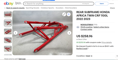
Found one on Ebay, that with shipping would be about $410. Would suck, but not crazy, all things considered, if it were really necessary to buy another one.
The pic in the ad shows the cross piece that connects to the other side, at about the point the top mount connects to the subframe. Not saying connecting to the aluminum subframe is a good idea, but as part of a system, it might be stronger than imagined.
It doesn't look like it would be all that difficult to replicate this subframe in steel. That might be on a future agenda, as I contemplate options for redesign.
If the current aluminum subframe breaks, that might accelerate that little brain fart. Otherwise, will probably leave it alone and just run with a new center top strut for awhile.
@ben-franklin I think your solution where you now clamp the upper mount around the subframe is probably good enough. Not relying on just two bolts now. Seeing as there is a link across to the other side. It should transfer a lot of load over. Maybe a plate or struts fabricated from the two forward mounts where it attaches to the rest of the frame tied into your now modified mount..I think you are planning on using these two for your 5th strut mount, Right?? Maybe incorporate it all together. Maybe a triangle it across to the other side some how would be the only thing to make it stronger.. Probably not feasible.
Well friends,
All is right in the world. Black Betty (that sweet girl) is back on her side of the garage, not being worked on in the TLC's spot.
Rode around running errands most of the day, after cleaning up the shop, reinstalling the bushel of zip ties required to keep wires and cables out of mischief, and reinstalling covers, heat shields, etc. (Winch still stays off for a little while, longer, though.)
Really liking the feel. I think there always was a little "spring" in the A arm clamps, that is now gone. Things feel tight and super responsive. It is easier to fly the chair, than it was, maybe because it lifts the wheel instantly, without delay when you crank it over.
Overall, put maybe 150 miles on her, since the repairs. Will go for a little run down the highway tomorrow and see if anything loosens up. Still plan to put the center (5th mounting point) in, just need to design and fab the mounts, and order the bits to attach it.
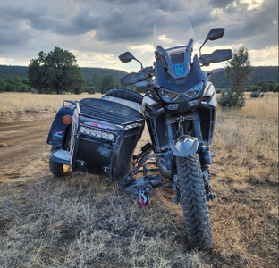
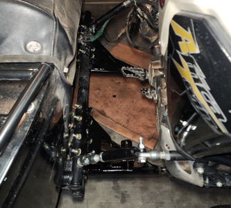
Under 2 weeks from this:
to this:
Thanks again Jonny! @sidecarusa ![]()
- 29 Forums
- 11.9 K Topics
- 93.5 K Posts
- 2 Online
- 5,612 Members


