I have a new sidecar rig. The joy of the new, lead to the inevitable desire to make it my own and better. I thought the new leading link front suspension was a bit harsh so I began by doing the usual preload and tire pressure changes to see if I could get what I was looking for in the ride and handling. Having gone through that without getting the result I wanted, I began more drastic changes.
I began by noting the traditional suspension markers used on telescopic forks, Static and dynamic sag and hoped it would roughly apply to the new suspension.
When I say harsh, I felt the front didn’t roll over small sharp rises like expansion joints in the pavement standing an inch or two tall, but rather slammed into them, and “Fell” into pot holes. There was little “compliance”. The result was a harsh ride and some handling issues. So, let us see what I can do about it.
The first datum is the free sag. It is the amount of movement the shock makes from free (wheel off the ground) to the amount the suspension compresses under the weight of the bike and rider. Then I needed the amount of compression caused by dynamic forces; a ride down a bumpy road.
The bike alone weighs a bit over 288 Kg (635 lbs) with a front wheel weight bias. I didn’t have a set of three scales to get an exact weight distribution so I was guessing the three Hagon shock/Spring units were too heavily sprung with 45 Kg/cm springs (252 lbs/inch each). There is a small leverage consideration with the leading link setup, but I will get to that later. A quick went email to Hagon Sales and I had a reply in a day. They suggested 40 Kg (224 lbs/inch) or even 35 Kg (196 lbs/inch) springs would give me what I wanted on the front end of the rig. This was based on the following test numbers:
45 KG springs: 1 mm free sag, and 21 mm dynamic sag.
Free sag is the amount of compression of the spring between it fully extended, and the compression with the weight of the bike and rider. Dynamic sag is the amount of compression caused by the movement of the whole wheel and suspension after a ride. In my case it was a five mile trip down a local 45 mph road that is quite rough with winter damage, two roundabouts, and a short 60 mph stretch of four lane.
I ordered two sets of springs, one set of 40 Kg ( and a set of 35 Kg at the suggestion of the helpful people at Hagon. They arrived in a week, from the UK. I then set out to run my experiment. I changed out the springs for a set of 40 Kg springs and re-measured the free and dynamic sag and found the following numbers:
40 Kg Springs: 2 mm free sag, and 22 mm dynamic sag.
The ride quality was a bit better but not yet to my liking. It was still harsh and not compliant. So, on to the 35 Kg springs.
35 Kg springs: 6 mm free sag, and 25 mm dynamic sag.
Ok. So now if feel like I am getting somewhere. The ride was much improved with the front wheel riding over the expansion joint bumps nicely without the feeling that the wheel was leaving the ground after the bump. Pot holes felt like the wheel extended into them and rode up smoothly out of them. I don’t believe trying a 30 KG spring would give me a better ride and may turn out to be too soft.
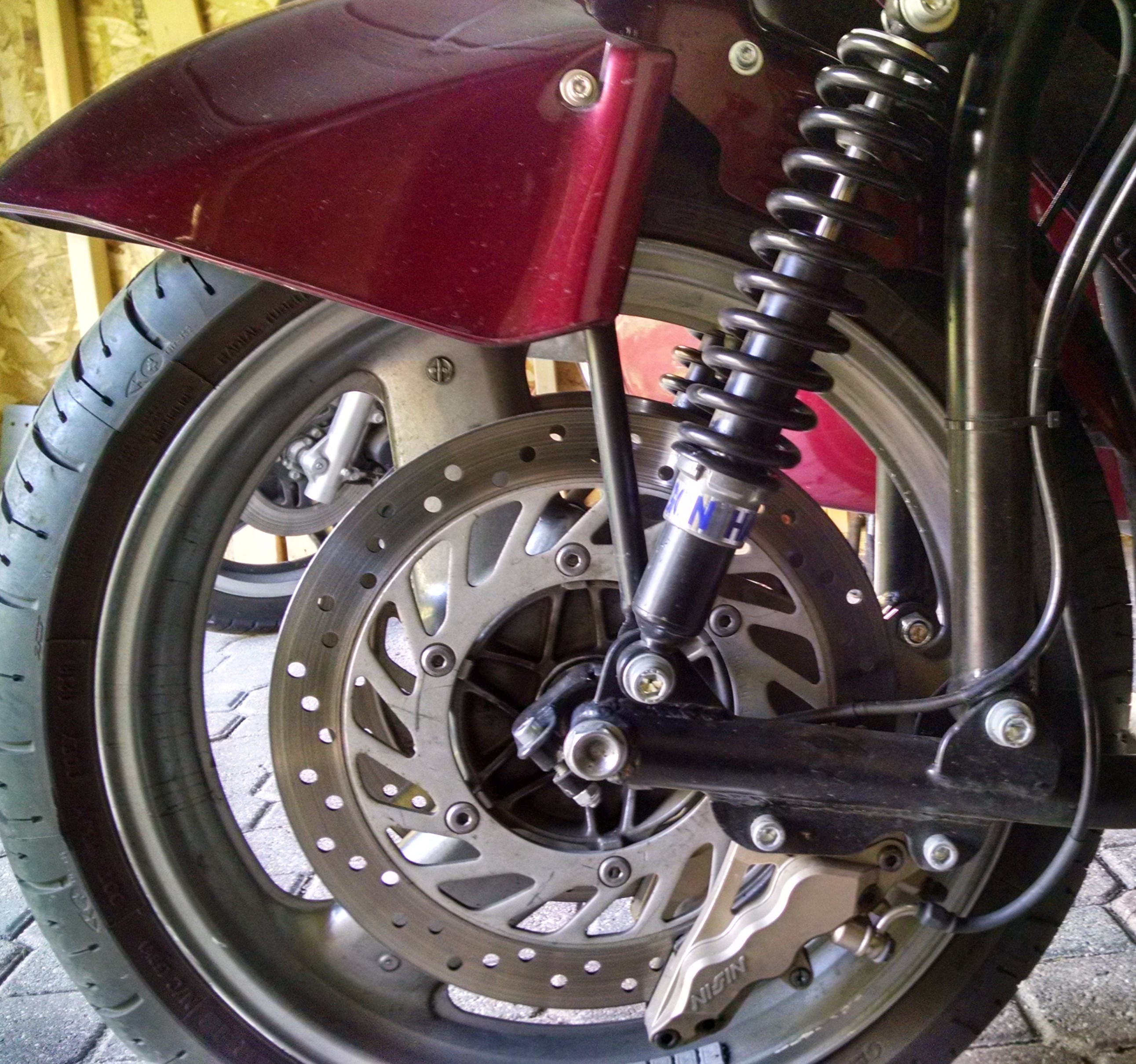
ith the leading link there is a lever arm. The wheel will move an additional 2 mm with each 1 mm the shock compresses or extends. So the actual movement of the wheel is slightly greater than the shock travel.
I measured the shock travel by moving the bump stop rubber bushing down the shaft to the top of the shock cylinder. Any compression of the spring will move the rubber bump stop up the shaft. It was difficult to get an exact measurement, but by “eyeballing” the gap between the top of the cylinder and the bottom of the bump stop, compared to a metric scale, I could estimate the compression travel within +/- 1 mm.
Changing out the springs was accomplished with the technique from a Youtube video using no special tools, just a pair of ratchet straps. Many thanks to the fellow who posted the suggestion.
https://www.youtube.com/watch?v=LES7YJ5hYxo
Through all of this I didn’t change anything with the sidecar shock and spring. I then thought to document the baseline to use for further changes. It has the following numbers:
Sidecar 45 Kg spring: Free Sag 3 mm, 6 mm static sag with passenger, 28 mm dynamic sag with a passenger. On this suspension there is no leverage advantage. The wheel will move the same distance the shock compresses.
I will try a 40 Kg spring on the car, but I feel the amount of centripetal forced lean on left hand turns is wielding substantial sag on the unit; 28 mm (1.1 inches) with a passenger. That would leave some suspension travel for additional weight and bump severity before the shock reaches full travel.
I admit that if I had started with more measurements, like the weight distribution. I could have gone to a specific spring rate without having to experiment and would have saved a few dollars on the second set of springs. But where is the fun in that.
Jim
Jim, I like to read from like-minded people like you.
I've done extensive research on the matter of suspension for my two-wheeled Ducati Monster 1200S, and written about it on my blog. Alas, it's in German.
This much I can tell you right now:
It's never too late to insert some precision, by doing the measurements and thinking things over. Measuring wheel loads, for instance, can be done sequentially, one wheel by one. You can add up the three separate measurements for the total (empty) weight of the rig, without loss of precision.
As far as the "static sag" is concerned:
the rule of thumb is: 30% of total travel for the static case (empty rig plus driver) in a sportive setup, 35% for a more comfortable touring setup. Note, that the total amount of possible spring compression is not determined by what you have observed during test rides, but rather by what the specs of the damper's physical properties are.
Since some kind of leverage is involved, be sure to keep the travel of the front wheel axis apart from damper (and spring) compression. A picture from the side having as little as possible parallactic distortion would be great. Use a tele lens from a great distance for that. Like so:
If done properly, you can take the necessary measurements with sufficient precision from the picture later on.
ChrisK,
Thanks for the tip. Your post also pointed out a critical data bit I did not include. The total travel available on the shock to the bump stop is 70 mm. The 25 mm of dynamic sag with the 35 Kg springs is the 35% that should be what the static sag value should read?
Before I converted this bike to a rig, I had a set of Traxion Dynamics cartridges and springs installed. The static sag on the telescopic forks was near the 25 - 30% range. So here is where I confess I am unschooled in the physics of the leading link system. I will take your suggestion to measure each wheel independently and look at the system again. Perhaps the 30 Kg springs will be more to my liking after all.
Jim
Jim, yesterday I threw you just a few quick "bones" from what I instantly remembered at that time. Actually it is a little more involved than what I wrote, and to make matters more complicated: there's not only the spring rate, but also the preload adjustment that needs to be taken into consideration. Meanwhile I refreshed my mind from what I wrote in my blog.
These are the steps I followed during my investigation:
- Determine the wheel load of the empty rig (without rider) at the front (only). A hydraulic engine hoist like this is very handy for that.
- Adjust both spring preloads to the same setting, such as there is at least a minimum sag when you lower the front wheel of the empty rig completely from the hoist.
- Record the length of a spring and write that down 😉 Both springs should have the same length, btw.
- evaluate the unsprung weight of the front wheel. Because that doesn't contribute to the compression of the spring. The way to do this is fairly simple: hoist the front wheel from the floor - 2 inches should be sufficient. Remove the screw connecting the lower end of one damper from the leading link, then remove the screw connecting the upper end of the other damper from the fork leg. The reason for this is, that the damper itself partly belongs to the unsprung weight, partly to the sprung weight. Then take a reading of the weight of the "loose" front wheel, including double disc brake plus calipers, fender, a share of the leading link, as all are not supported any more. I expect the reading to be in the 25+ kg range. Write that down, too. We're going to need this later on. Re-connect everything to the prescribed torques, then lower the front wheel completely.
- Sit down on the tug machine. Since you'll be sitting centered (left-to-right), the side wheel will not pick up any of the additional load.Your weight will be absorbed by the front and rear wheel only. I expect a weight distribution of between 45% and 50% of your weight on the front wheel, and between 55% and 50% on the rear wheel. If you want to know exactly, you'll have to perform the wheel load measurement again, this time with you being seated in a typical riding position. You'll need a 2nd person to help you for that, raising the hoist, placing a scale, lowering the hoist and taking the reading, all the while you'll still be sitting in the typical riding position.
- Again, record the length of a spring (with you seated on the bike) and write that down, too 😉
At this point you'll have a "delta wheel-load" and a "delta spring length", which is the very definition of a spring rate. A few things to note here:
- you are having two springs, which work in parallel, in which case the individual spring rates can/must be added: two springs of 35kg/cm each are equivalent to one spring of 70 kg/cm.
- It is the static compression of the spring(s) under the rig's plus your own's share of weight for the front wheel, which should make up 30%-35% of the total possible damper travel. The dynamic travel is divided into negative and positive travel, which in sum account for 100% of the dampers physical travel limit. The mentioned 30%-35% provide room for the "negative travel", that is: expansion of the damper, when traveling across a pothole. The remaining 65%-70% of damper travel provide for a positive compression when running across positive steps.
- The wheel load is measured at the wheel contact point with the floor surface (same as at the wheel axle), while the spring load (and compression) is measured at the spring. Your leading linkage creates some kind of a geometric leverage between the two frames of reference, the ratio of which you'll have to figure out by means of a better photograph that what you provided. Hint: imagine the bike had a hollow front axle. Take the fotograph from a position from where you could look right through that axle, from as far away as possible. Please include the steering head part of the frame in that photograph, too.
Good luck and please do keep us posted.
Chris
ChrisK,
I dug a little deeper into the front suspension after reading the information above, and the blog in the link. My tools and methodology may not be precise enough to dial down to the last detail, but practical riding and a bit of "good enough" back yard, shade tree methods has me satisfied with the set up as it is.
I did not have a scale able to read the weight of the front end. Calls to some old race buddies failed to turn up a scale capable of the task. So I employed a bit of leverage. A short bridge, a scale, a fixed block at the other end, and the contact point of the wheel in the center of the bridge. A bit of arithmetic was employed to double the scale reading. I did block up the rear wheel to keep the tug level when on the "bridge". I used my hydraulic floor jack for lift and release.
I started a few other changes. The rear tire was worn beyond what I normally allow so I chose a replacement. The Pilot Road 4 GT low profile dual compound radial was exchanged for a Commander III 160 17B70 profile bias tire, and a 130 18B70 front to replace the PR GT4 there. This meant I needed to re-adjust the lean-out on the rig as the tires make the tug sit higher. The much heavier front tire did increase the steering effort slightly and made the steering less twitchy. The heavier tire seemed to smooth the ride some. Perhaps the added un-sprung weight helps "decompress" the suspension when rolling off an edge.
Total weight: 396lbs / 183 Kg
Un-sprung Weight: 22 lbs / 10 Kg
My weight in riding gear: 180 lbs / 82 Kg (half on the front wheel 41 Kg)
Weight on the front suspension: 334 lbs / 152 Kg
Spring rate at 35 Kg (35 Kg/cm X two springs: 70 Kg/cm)
Well, Thanks for the help. I did manage to get a few hundred miles in after our early snow melted. A few more days of riding weather are ahead, but ultimately, this is near the end of the riding season here in the great frozen Northland. I won't be able to put many more miles on it before packing it in for the next five or six months.
Jim
Jim,
a digital body scale with a range of up to 180 kg can be obtained via eBay for as little as US$ 20.- That's a really modest investment for a lot of precision in return.
And the unsprung weight of your front wheel (10 kg ?!) seems significantly under-estimated! Just think of tire, rim, front axle, two brake disks, two brake calipers, a share of the leading link, one of two front shocks, the front fender, just to name the most obvious contributors.
If you're happy now "as is", don't bother any further.
Chris
I read your reply and my error clicked into awareness.
I forgot to double the un-sprung weight measured on my lever arangement.
Jim
Or if you are interested in rolling your rig onto a heavy-duty scale - here's an option. 3 would let you measure weight easily on each wheel at once in various configurations - with and without passenger, luggage, etc.