@dwitgoldwing Make sure that there is enough clearance for the tilt/pivot mechanism. My FS l has the hole in the frame for the actuator mount, but I'm pretty sure there is not enough room between the tub and frame to mount the pivot.
tvking63 & dwitgoldwing - the beauty about the tubs is they are fibreglas, so easily repairable... or relatively easy to modify, if you're handy with working with fibreglas & polyester resin. Shouldn't be too much work to cut away/relieve where the tub contacts (gets in the way) and then lay up a fibreglas bubble to enclose it again.
dwitgoldwing - I just took a bunch of close-up pics of the actuator pivot mechanism for you. The distance bolt centre to centre is 5 1/4". I put a machinists ruler beside so you can scale appropriately. Shoot me an e-mail & I'll send you full resolution pics. The site auto scales the resolution down - my actual pics are much clearer.
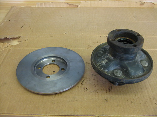
I'm attaching a good crisp pic of the back of the wheel hub assembly. I don't see where a rotor would attach - am I missing something? Also, note in the 1 pic I found some hard rubber donuts to use as spacers between the tub & frame - they are 1 3/4" dia rubber cups you use as floor protectors for under furniture legs. They look like they'll be perfect for the purpose. E-mail DarylunderscoreMartel@shaw.ca
Just got a reply from Scott Turner at CSC. His answer: "The hub came from FIT BEARING out of California. The brake caliper and the brake rotor came from MOTOR QUALITY out of Italy.(Brembo) Sorry I do not have an address or a phone number to give you."
I'll look back thru the thread and see if we have a good pic of the stock hub/rotor. If not, Mike, did you take a pretty clear pic?
The hub came in with out the ring welded to the rear. Brembo will not sell dirrect and they sold the rights to the FO4 calipar several years ago. The company they sold the rights to made the FO4 calipars for a few years and stopped making them.
Jay G
DMC sidecars
866-638-1793
Thnx Jay. Bit of a dead end then, eh. I'm not too keen on messing with welding new caliper mounts on... just yet. That may change after I have a few miles on it.
What we can supply, Hub with a brake rotor, the new type of brembo calipar, a CNC cut bracket to weld onto the swing arm, the brake hose with a double banjo bolt. The hub will have either a 4 bolt on 4 inch pattern or a 5 on 4.75 pattern, your choice. $500
What you would do is assemble every thing, apply brake pressure to hold the calipar in place while welding the bracket on.
Jay G
DMC sidecars
www.dmcsidecars.com
866-638-1793
Here is the best I can come up with.
Daryl Martel - 12/22/2011 3:39 PM
I'm attaching a good crisp pic of the back of the wheel hub assembly. I don't see where a rotor would attach - am I missing something?
No, you're not. Now that I have a better pic of your hub, I can see that you don't have the mounting collar on yours. The only way I know for you to add brakes now, is to buy and new hub ,rotor, caliper and bracket from Jay and weld up a new mount. I guess you could fab the collar and weld it to your hub, but it would have to be machined perfectly true to keep rotor runout to a minimum.
Here's a pic of my hub with the rotor mounting collar and the rotor from DMC.
Thnx everyone for all the info, and pics. Jay, I will wait to see how it goes before comitting to buying. Having never driven a sidecar (yet), I am concerned about the added weight/mass and emergency braking situations. Am sure looking forward to getting it on the road.
Well, let me chime in and say I've been concerned about what the dynamics are going to be of adding my Friendship III sidecar to my GL1200. It is definitely going to take some getting used to judging from the tons of articles I've read on the subject in the last 2 months.
From what I've read, I am definitely going to wait to install my car until AFTER I get my sidecar brake system worked out and installed on the frame and working properly. I will not even ATTEMPT to drive my rig without a properly functioning sidecar braking system. It just makes sense to me that if you have a couple hundred pounds plus rider/luggage sitting to the right of the bike, you better have some way to stop all that rolling mass. I've gotta believe you will DEFINITELY feel the sidecar pushing when trying to stop. I am fortunate that my sidecar already has the brake/rotor system installed and all I have to do is mount my master cylinder and extra pedal to my sidecar frame.
I chose to have the extra pedal instead of plumbing into my bike brake system. I just see having the sidecar on it's own system making a lot less headaches when riding without the sidecar. I will just have to disconnect my mounts and then off I go; no worrying about bleeding the bike brake system every 3 or 4 rides.
I fully understand the economic concerns of adding the proper brake cylinder/rotor/hub setup, especially since I've been unemployed twice in this last year. Still, through odd jobs and stuff I've been able to get my whole brake system together and am working on mounting right now. I just gotta believe it will be WAY less scary having brakes on my sidecar, than having none at all. I don't even want to try and learn to ride a sidecar setup without brakes.
Best wishes to you... Please let us know how this all works out.
Thanks VERY much for all the pics of the Electric Lean setup. I am working on adding that to my FS III so I will have the best of everything, that way when I go riding with my CSC Friendship III sidecar and my fiance, WE MAY JUST NOT WANT TO COME BACK!!! 🙂
Just in case anyone is wondering what to do with all those wires, I just found the color codes for mine. I can't swear it will be right for all of them, but it is labeled Friendship 2 and 3.
First color is primary, second is a trace or stripe
The white and yellow wires are spares and go to nothing.
Brown/White is the ground wire
Blue/White is the front white light, tail, and marker lights
Purple is the turn signal
Blue/Black is the brake light
Green/White goes to the back up light
Pink is a hot wire to power the radio's clock and memory (sometimes cigar lighter)
Red is a fused accesory line to radio and sometimes cigar lighter.
If your lighter works with the key off, it feeds from the pink. Otherwise it's the red.
Yellow/Black is the UP position on the electric lean
Blue is the DOWN position on the electric lean
Purple is the electric fuel pump.
Hope this is of use to someone.
Jeez Mike - you are one timely guy! Was just looking at my harness this afternoon wondering how I'd figure out what does what. There sure are many more wires than needed, and weird connectors too (think I'm going to cut 'em off). It'll take me some time to get done connecting mine, but when I do, I'll be able to report back whether that colour coding is consistent on mine too.
Hey Daryl,
I don't know if this will help on your 1500, but here is how I wired my hack to my 1100.

A little explanation;
I used a "flat 4" to wire the lights attached to the frame and a "square 6" to wire the tub. The idea being that I could run the frame without the tub and a car top carrier or other cargo in it's place.
The tub has a dual-intensity red brake/tail light and an amber single-intensity light in the nose for marker/turn.
The tub also has two power circuits for accessories that the Mrs might want (cell phone, fan, hair dryer, heater, waffle iron, etc) 😀
The SPST relay up top is there as a "power relay" tied into the ACC circuit of the bike. It basically allows me to power the tub via it's own fuse block instead of tapping off the bike's block.
the SPDT is there since I'm using a dual-intensity LED fixture for three functions - tail, brake and right turn. When R.MARKER is ON, the relay passes BRAKE, otherwise it passes R.TURN (marker off, turn on).
The two diodes prevent feedback between the R.MARKER and R.TURN supply signals.
I use a couple of LED "Driving Lights" to serve as a headlight on the frame.
Let me know if you need more details!
Hi OldSchool aka Bruce - yeah, could use this info for sure too. I already have a hitch installed on my bike and use an isolator and 5 into 4 pin converter. I bought another one (it appears to be a combined unit) which I'm thinking of wiring in. Definitely will use at least one flat 4 pin plug for the connection, for the lights for sure. All the sidecar lights will be LED, so not too worried really about current draw. For the sidecar height adjust actuator however, I'm thinking there should be relays in the circuit to reduce arcing on the switch... and maybe another "switched" relay for the cigarette lighter. My big fear is having something on the hack drain the bike battery when parked. I like the idea of keeping a spare fully charged battery in the hack as back-up should this ever occur.
A couple capacitors (aka condensers) could be used to prevent arcing too. That's how it is done on older ignition systems to prevent arcing points. Since I own a couplea Honda CB's, I'm familiar with the technique! 😀
