For some extra information about navigating the forum you can go to Forum Tips
Wiring and lighting
Quote from Buckaroo on March 19, 2017, 4:33 pmI have the car on and tracking fairly well. Today I started on the wiring and have a few questions before I finish. I am going to run all new wiring because the original wiring is all put together with crimp connectors and I want to solder everything.
While I am in there I am going to add a cigarette lighter for charging and a switched light in the trunk. Is there anything else I should consider ?
Also there was a inline switch in the sidecar wiring, why would you want to do that ? Why not just use the bike switch ?
I have the car on and tracking fairly well. Today I started on the wiring and have a few questions before I finish. I am going to run all new wiring because the original wiring is all put together with crimp connectors and I want to solder everything.
While I am in there I am going to add a cigarette lighter for charging and a switched light in the trunk. Is there anything else I should consider ?
Also there was a inline switch in the sidecar wiring, why would you want to do that ? Why not just use the bike switch ?
Quote from Deleted user on March 19, 2017, 5:16 pmDoes the car have a running light and taillight/turn signal/brake light? The cigarette lighter/12volt outlet is a great idea. We ran one in our k1100/Motorvation rig for all the time we had it (20+ years). The in-line switch is un-neccessary. I always had a plug under the seat to disconnect the rig wiring for when I had to take off the car. A 4 contact flat trailer plug works well and is readily available at any hardware or auto parts store. Shoot - I bet you can get it at Walmart.
Does the car have a running light and taillight/turn signal/brake light? The cigarette lighter/12volt outlet is a great idea. We ran one in our k1100/Motorvation rig for all the time we had it (20+ years). The in-line switch is un-neccessary. I always had a plug under the seat to disconnect the rig wiring for when I had to take off the car. A 4 contact flat trailer plug works well and is readily available at any hardware or auto parts store. Shoot - I bet you can get it at Walmart.
Quote from Al Olme on March 19, 2017, 9:14 pmThe four connector plugs work OK if your setup is simple. I find that I need more. Figure out what you want and how many devices can share a circuit. In my sidecar I have...
1. Brakes
2. Tail light/front running light
3. Outlet/charger
4. Interior light sidecar and interior light trunk
5. Sidecar mounted driving light [in my configuration there is an additional wire for a dimming circuit on the driving light but that's really uncommon.]
6. Ground
(7 & 8) - extra wires for future expansion or an intercomTo make things neat, I use a barrier strip mounted in the sidecar trunk. I ran eight separate wires through a single heat shrink sheath. wires 7 and 8 aren't connected to anything at the moment. #6, the ground wire is a larger gauge than the others as it is a shared ground to everything. By using the barrier strip, I can make neat connections for the shared items like the interior and trunk lights. Wires #3 and #4 are supplied through a relay that makes contact when the bike headlight is turned on so I can't run the battery down by forgetting to turn something off. Also, those are fused and could be combined if you really want to.
I used marine grade wire, but then, I'm a worrier. Marine grade is tinned for the entire length inside the insulation and is less likely to corrode when damp.
Good luck.
The four connector plugs work OK if your setup is simple. I find that I need more. Figure out what you want and how many devices can share a circuit. In my sidecar I have...
1. Brakes
2. Tail light/front running light
3. Outlet/charger
4. Interior light sidecar and interior light trunk
5. Sidecar mounted driving light [in my configuration there is an additional wire for a dimming circuit on the driving light but that's really uncommon.]
6. Ground
(7 & 8) - extra wires for future expansion or an intercom
To make things neat, I use a barrier strip mounted in the sidecar trunk. I ran eight separate wires through a single heat shrink sheath. wires 7 and 8 aren't connected to anything at the moment. #6, the ground wire is a larger gauge than the others as it is a shared ground to everything. By using the barrier strip, I can make neat connections for the shared items like the interior and trunk lights. Wires #3 and #4 are supplied through a relay that makes contact when the bike headlight is turned on so I can't run the battery down by forgetting to turn something off. Also, those are fused and could be combined if you really want to.
I used marine grade wire, but then, I'm a worrier. Marine grade is tinned for the entire length inside the insulation and is less likely to corrode when damp.
Good luck.
Quote from OldSchool_IsCool on March 20, 2017, 9:09 amHere is what I did. I used a flat-4 trailer connector for all things on the hack frame and a square-6 for all things in the car itself. I wanted to keep the frame and car connectors separate because my car is easily dismounted from the frame and I plan to build a flatbed that can go on in it's place for hauling cargo and for possible wheel chair use. Having the car on it's own connector makes the swap easier. The tug is a Goldwing 1100 by the way.
The top relay is connected to the ACC feed on the bike. It goes live when the key is turned on. A fuse block then feeds power to "Hack Power 1" and "Hack Power 2". A third fuse is switched and used to power auxiliary head lights on the frame. Other connections on the square-6 feed a front marker light and a second tail/brake light that is mounted high on the car like an automobile's 3rd brake light. The HIGH and LOW you see is for brake lights and running lights respectively. Then finally there is the ground connector.
On Goldwings (and I assume many other bikes) the marker light turns off when the turn signal is activated. The bottom relay and diodes are there to do that same function for the hack. It basically converts the brake light (LED High) into a turn signal.
Here is what I did. I used a flat-4 trailer connector for all things on the hack frame and a square-6 for all things in the car itself. I wanted to keep the frame and car connectors separate because my car is easily dismounted from the frame and I plan to build a flatbed that can go on in it's place for hauling cargo and for possible wheel chair use. Having the car on it's own connector makes the swap easier. The tug is a Goldwing 1100 by the way.
The top relay is connected to the ACC feed on the bike. It goes live when the key is turned on. A fuse block then feeds power to "Hack Power 1" and "Hack Power 2". A third fuse is switched and used to power auxiliary head lights on the frame. Other connections on the square-6 feed a front marker light and a second tail/brake light that is mounted high on the car like an automobile's 3rd brake light. The HIGH and LOW you see is for brake lights and running lights respectively. Then finally there is the ground connector.
On Goldwings (and I assume many other bikes) the marker light turns off when the turn signal is activated. The bottom relay and diodes are there to do that same function for the hack. It basically converts the brake light (LED High) into a turn signal.
Quote from Al Olme on March 20, 2017, 11:16 amOldSchool,
That's a nice clean way to do things. You could have the same function out of just the flat 6 but that would add complexity and there's plenty to be said in favor of nice clean direct wiring. Good job.
OldSchool,
That's a nice clean way to do things. You could have the same function out of just the flat 6 but that would add complexity and there's plenty to be said in favor of nice clean direct wiring. Good job.
Quote from DRONE on March 20, 2017, 9:33 pmBuckaroo--you say you want a switched light in the trunk. The normal techno jargon when wiring bikes and boats and whatnot is that each electrical circuit is either switched or unswitched. A "switched" circuit means it's HOT when the bike is running, or optionally, when the bike's ignition switch is turned on. An "unswitched" circuit is one that's hot all the time 24/7. I'm guessing what you really want in the trunk is an unswitched circuit but with a light that you can turn on and off manually.
When you say there is an inline switch in the sidecar, you mean some sort of manual on/off switch? I wouldn't guess why that would be there without knowing what device was controlled by that circuit. So, what does that circuit connect to?
Like what the other guys said, when wiring up a sidecar, decide in advance how you're gonna do it. You can use an auxiliary fuse box in the car or on the bike, you can use inline fuses, or you can do some sort of combo. You can use individual circuits for each gizmo, or you can share one circuit with several gizmos.
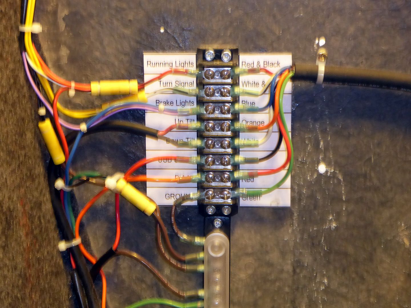
I just finished a sidecar wiring project where I used 8 wires from the sidecar to the bike. One was a ground wire, which was redundant since I also grounded everything in the sidecar to the frame, and for the other 7 lines, some went to an aux fuse box mounted in the bike, some went directly into the bike's harness, and some went directly to the battery. It's all about the planning.
Here's what my power distribution looks like behind the seat--->
The 7 circuits are running lights, turn signal, brake lights, electric trim up and down, USB socket (so the wife can have power for her phone, or so I can charge my phone while I'm riding), and auxiliary driving lights.
Buckaroo--you say you want a switched light in the trunk. The normal techno jargon when wiring bikes and boats and whatnot is that each electrical circuit is either switched or unswitched. A "switched" circuit means it's HOT when the bike is running, or optionally, when the bike's ignition switch is turned on. An "unswitched" circuit is one that's hot all the time 24/7. I'm guessing what you really want in the trunk is an unswitched circuit but with a light that you can turn on and off manually.
When you say there is an inline switch in the sidecar, you mean some sort of manual on/off switch? I wouldn't guess why that would be there without knowing what device was controlled by that circuit. So, what does that circuit connect to?
Like what the other guys said, when wiring up a sidecar, decide in advance how you're gonna do it. You can use an auxiliary fuse box in the car or on the bike, you can use inline fuses, or you can do some sort of combo. You can use individual circuits for each gizmo, or you can share one circuit with several gizmos.
I just finished a sidecar wiring project where I used 8 wires from the sidecar to the bike. One was a ground wire, which was redundant since I also grounded everything in the sidecar to the frame, and for the other 7 lines, some went to an aux fuse box mounted in the bike, some went directly into the bike's harness, and some went directly to the battery. It's all about the planning.
Here's what my power distribution looks like behind the seat--->
The 7 circuits are running lights, turn signal, brake lights, electric trim up and down, USB socket (so the wife can have power for her phone, or so I can charge my phone while I'm riding), and auxiliary driving lights.