Ladies, Gentlemen,
this is my 1st post and I would like to briefly introduce myself:
I'm 60+ years old, mechanical engineer by profession/education, German by birth and Swiss by choice. Been living in Switzerland for almost seven years now.
Long-time (40+ years and 200k+ miles of experience) biker on two wheels, currently and last 5 years on a Ducati Monster 1200S. Additionally I have joined the ranks of sidecar enthousiasts two years ago, on one of the twenty only (worldwide) copies of the Ural cT "Transsib" special edition of 2018. I'm also the author of the non-profit blog "vielzutun.ch", where I write about various bike and sidecar-related topics, along with my wife, who covers knitting and crocheting. Our blog is written in German.
That said:
I have only recently found this site, and have superficially sifted through the "Technical" section. I see interest in weight distribution issues, chassis dimension issues, fear of tipping over issues and general "how to ride a sidecar bike" questions.
This is where I believe I can contribute and drag some of the answers out of the (IMO) rather shady "experience" and "trial and error" realm. I have developped an "Interactive 3D Sidecar Simulator", which computes(!) and visualizes in interactive 3D-Computer graphics the tipping limits of generic motorcycles with a sidecar. And sorry, folks, this covers only genuine sidecar bikes, with a sidecar truely to the side of a motorcycle, but no generic trikes. Neither two-wheel front, one-wheel rear variety, nor the one-wheel front, two-wheel rear variety.
And, another caution: my blog vielzutun.ch and the aforementioned Interactive 3D Sidecar Simulator are currently only available for german-speaking/understanding audience. Since my simulator has been introduced to the public in the current edition 179 of the german sidecar-magazine "Motorrad-Gespanne", it has attracted considerable interest. So I thought, it would be a good idea to make it available for the english-speaking community as well, depending on feedback and/or expressed interest.
I understand, that you'll nevertheless need some intro to get you started with the currently german-only version.
So the first thing to consider is, that this simulator and its computations are based on the SI-System of measurement. Which is "Gramms" for masses, "Meters" for distances, "Seconds" for times. Plus of course their power-of-ten fractions or multiples like "kilo", "milli" and so an.
Then there is the basic concept of this simulator as such:
It works in a three-step approach:
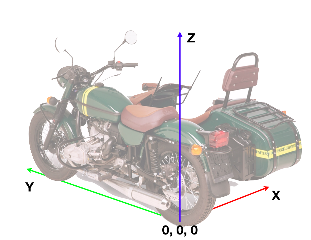
1st we need to determine the exact 3D-coordinates of the center of gravity (CG) of the empty rig in the following coordinate system:
This is accomplished by individually weighing the wheel-loads of the rig: front, rear, side.
Then we need the chassis dimensions: wheel base, track width, lead.
This will give us the x-y coordinates of the CG already.
To determine the elevation of the CG above the road, we use the "tipping"-method: lift the sidecar up until you can balance the rig between "two fingers" above the connecting line between front and rear tire. Measure that angle (against the horizontal), and the elevation (z-coordinate) of the CG follows from a simple computation.
Now you have the precise 3D coordinates of the CG of the empty rig.
2nd comes the displacement of the CG, when you add additional masses to the rig. Like rider, sidecarist, pillion passenger and/or up to two freely placable loads like luggage or rig modifications.
These additional loads add both to the total weight, plus shift the new(!) CG to a different position in 3D-space. This can be computed to perfect accuracy, if you provide the mass and coordinates of the respective CGs of the additional masses.
3rd: you need to be aware, that all forces acting on the combined rig plus additional loads can be considered as acting on the combined CG itself. The external forces are:
- gravitational, acting straight down
- inertial, from acceleration or braking, acting along the direction of travel
- centrifugal, from riding along a curved path, acting transverse to the direction of travel.
Fortunately, these forces can be mathematically combined into a "resultant", which again acts upon the combined CG of the empty machine plus additional loads.
You'll probably have observed how a pendulum, hanging from the rear-view mirror of your car swings to the rear during acceleration, to the front during braking and towards the outside during curved ride. Now imagine, the pendulum was a laser pointer suspended from the center of gravity of your rig: The laser beam would at all times hit the floor whereever the current combined forces (gravitational, inertial, centrifugal) would point to.
The rig rests upon a (basically) triangular supporting surface, which is limited by the three points of contact of the three tires: front, rear, side.
If the laser beam hits the floor within that triangular surface, the rig is stable with respect to tipping. If the laser beam hits the floor outside of that triangular surface, tipping will occur unless the rider counteracts.
The combined range of all possible combinations of gravitational, inertial and centrifugal forces (within a range of "1 g" transverse to the direction of the gravitational force) is represented via a translucent cone, having an opening angle of 90°, originating from the combined CG, and pointing straight down.
Whatever you'll be doing in that simulation:
- varying the chassis dimensions (wheel base, track width, lead)
- varying the empty rig wheel loads (front, rear, side)
- varying the additional loads (rider mass and position, sidecarist mass and position, pillion passenger mass and position, additional load mass and position):
the effect of these variations will be immediately visible in the visualization.
The "cone" as described above projects a circular scale onto the ground surface, with the bulls-eye (0.0 g) being straight below the CG of the combined rig plus loads, and the "1.0 g" being at the outer edge of the outer ring. Each ring has a width of 0.1 g.
It is where the circular beam lights beyond the triangular support surface where tipping will happen. And it is the innermost reading on the circular scale, where the circular beam just barely touches the outer edge of the triangular support shape, which demarks the limit of how fast you can go around right turns. (The simulator also covers left turns, but that is a little bit more complicated and so let's leave that for an advanced lesson.)
As a last point: the simulator has been tested by myself for accuracy in real live. It has passed to my fullest satisfaction. 😎
So this opens up the simulator for predictive purposes:
- How fast can I go around a specific(!) right turn, defined by its radius of curvature, before hitting the tipping limit?
- How much ballast would I have to add if I wanted to turn that same corner at a specific faster speed.
And so on. There's definitely a whole lot more which has been covered (in German) and would have to be translated as well, but I hope you'll get the idea.
Click me!

Chris, many thanks for posting this subject. Am sure many much more educated than me will jump in with their opinions and comments.
Thus will make for an interesting discussion. Okay engineers, what say you?
Chris, First off I used google translater and everything change to english for me. Thank you for sharing
Dave USCA president
I think this would be a good thread for Peter Pan to join the conversation....
Congratulations Chris,
I looked into the program a few weeks ago when it got presented on Dreiradler-forum. As the variations of rigs in Europe are WAY more diverse it has very good applications. ... but I am too keen on old style rigs. 😉
With those we have more fun already at street legal speed. While the super rocket rigs are a "acquired taste".
Says the monkey nut, which connects handlebar with seat.
Sven
Quote from Peter Pan on September 21, 2020, 11:54 amCongratulations Chris
Sven, thanks for your praise - almost makes me blush 😉
Being new here and reading the "social fabric" of a forum not being my core competency, I still sense that you, Sven, are something like a gray eminence, and your endorsement of the sidecar simulator is probably something like the "go ahead" with it for everyone else around.
So, @everyone:
If you need any clarification, please do ask me via this forum or via private email, and I'll be happy to elaborate.
Hello Chris,
Junge lass die Honigschmiererei sein. Ich schau nur über den Zaun.
And am interested about what will come out in the end as practical result. Once you include road conditions and speeds there might come out a ride condition simulator and tool for accident analysis.
I always will remember the metallic rig model in BMVD "Leitfaden für Gespannfahrer". Your simulator has the change to grow into a digital version of it.
Sven
Quote from Peter Pan on September 21, 2020, 1:53 pmOnce you include road conditions and speeds there might come out a ride condition simulator and tool for accident analysis.
The "speed" has already been thought of in this simulator. I just didn't tell you yet 😉 Didn't want to overwhelm anyone upon first contact.
If used as intended, the simulator will give you a precise value of the marginally sustainable centrifugal acceleration at the tipping limit during right turns. It can also tell you about left turns, but that's an advanced topic, which I would rather cover at a later point in time.
Accelerations are colloquially measured as multiples (or fractions) of the gravitational acceleration on this earth, having the unit of "g", like in g-force. 1.0 g being the equivalent of the gravitational field of the earth itself. So a centrifugal acceleration of 1.0 g will pull you sideways with the same force, with which the earth pulls you down, which is what you perceive as your "weight".
For my Ural cT in stock condition:
- Wheel base (Radstand): 1485 Millimeters (mm)
- Track width (Spurweite): 1150 mm
- Lead (Vorlauf): 260 mm
- Tipping angle (Kippwinkel): 32.25°
- with myself als the sole "additional load", having a mass (Masse) of 82 kilograms (kg) @position(x,y,z) = (0, 520, 980)[mm].
the marginal centrifugal acceleration at the tipping limit is pretty exactly 0.4 g . See yellow dot on screenshot below:
How fast can I go, before I meet (or exceed) a centrifugal acceleration of 0.4 g ?
This depends on the radius of curvature that the combined center of gravity (CG) is moving on. And the sober fact of the matter is, that there is an infinite amount of (radius, speed) pairs which all yield the same centrifugal acceleration of 0.4 g .
I have prepared a little diagram, not only for the 0.4 g case, which shows the correlation between radius of curvature (along the horizontal axis) and the speed (along the vertical axis), for a bunch of distinct centrifugal accelerations, see legend on right side of diagram):
The 0.4 g line is the 4th from below.
As far as "road conditions" are concerned: at least the gradient can be simulated, too. See sub-menu "Steigung / Gefälle".
